Download PDF
Download page Ellipse Boxed: Mechanical specifications.
Ellipse Boxed: Mechanical specifications
Box units
General specifications
Overview
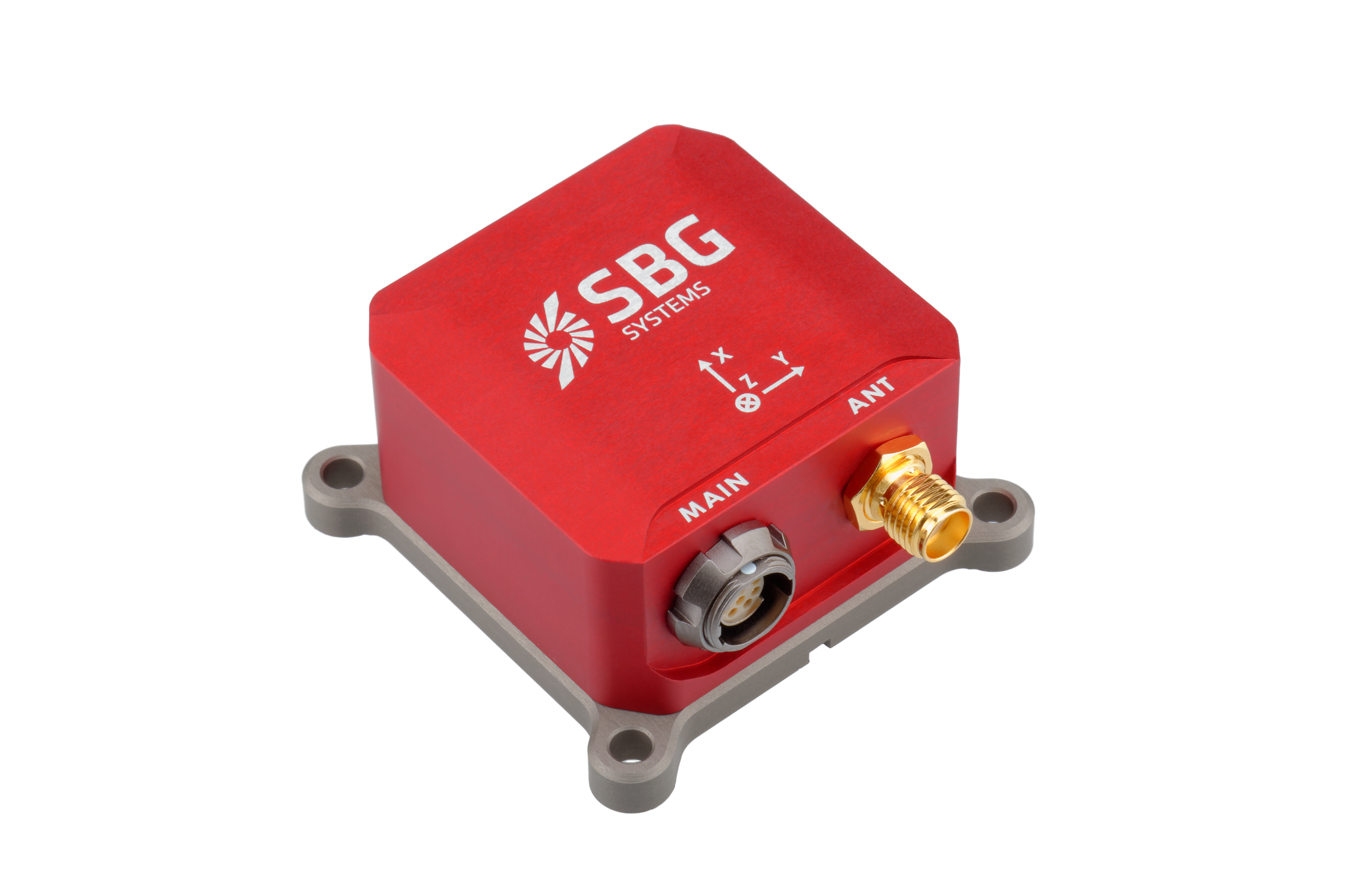
The Ellipse box units enclosure is composed of two anodized aluminum parts, one for the cover and one for the base plate. The device uses high quality alloys and connectors to offer a full IP-68 enclosure and a good resistance to harsh environments.
The Ellipse connectors are high quality Ultimate Fischer connectors that offers IP-68 protection even unconnected. The Ellipse-D version also includes two SMA connectors to connect the GNSS antennas. When used with a waterproof GNSS antenna cable, this connector offers an IP-68 protection.
Note 1
If you are planning to use Ellipse internal magnetometers, please make sure that you don't use ferromagnetic materials to mount the device.
Specifications
The table below summarizes all mechanical and environmental specifications.
| Item | Specification |
|---|---|
| Size | A, E, N: 46 x 45 x 24 mm D: 46 x 45 x 32 mm |
| Weight | A: 45 g N: 47 g E: 49 g D: 65 g |
| Shocks | Operational: 100g 6ms, half-sine wave Non-operational: 500g 0.1ms, half-sine wave |
| Operating Vibrations | 8g RMS – 20Hz to 2 kHz as per MIL-STD-810G |
| Environmental Specifications | |
|---|---|
| Enclosure | Anodized Aluminum |
| IP rating | IP-68 (1 hour at 2 meters) |
| Operating temperature | -40 to 85°C (-40 to 185°F) |
| Storage | -40 to 85°C (-40 to 185°F) |
| Humidity | Sealed, no limit |
| MTBF | 218,000 hours MIL-HDBK-217, Ground Mobile |
| Calibration interval | None required, maintenance free |
Device mechanical alignment
For best measurement accuracy, a good mechanical alignment is required. During manufacturing, the Ellipse measurement frame has been carefully aligned to 0.05° with the base plate for roll, pitch and yaw angles.
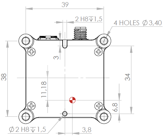
To ease the yaw alignment (Z axis), the base features two alignment holes Ø 2mm H8 that guarantees with two taper pins Ø 2mm h7 a yaw alignment better than ±0.05°.
Sensor (body) coordinate frame
This frame is attached to the IMU.
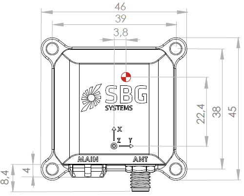
The following diagram shows the body coordinate frame as configured by default. In most situations, the body coordinate frame must be aligned with vehicle coordinate frame. Sensor alignment in vehicle can be rotated by software if the sensor coordinate frame cannot be aligned mechanically.
Check our Operating Handbooks for more information on the product configuration.
Origin of measurements
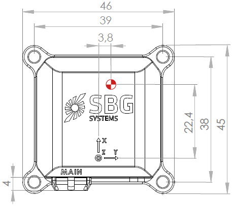
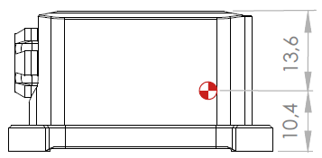
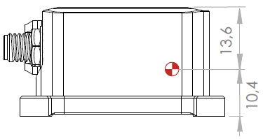
The center of measurement is not represented in the image above. The center of measurement for acceleration, velocity and position is represented on the mechanical outlines by the ![]() symbol. It is referenced to the base plate fine alignment hole.
symbol. It is referenced to the base plate fine alignment hole.
All lever arms should be measured from that point.
Mechanical outline
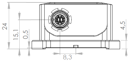
Ellipse-A mechanical outline
All dimensions are in mm.
Front view
Top view
Right view
Bottom view
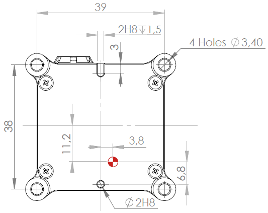
Ellipse-E mechanical outline
All dimensions are in mm.
Front view
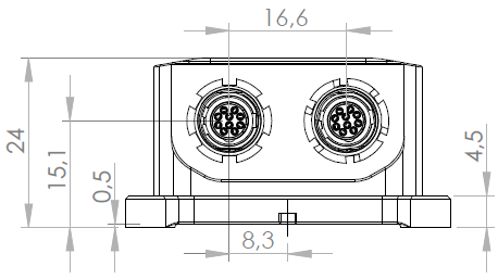
Top view
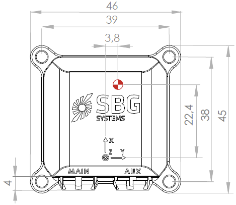
Right view
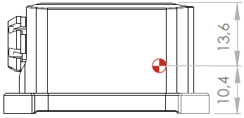
Bottom view
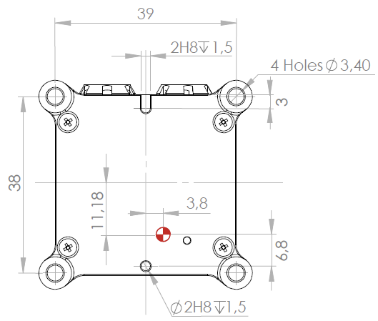
Ellipse-N mechanical outline
All dimensions are in mm.
Ellipse-N front view
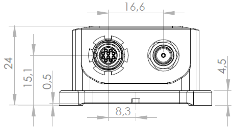
Ellipse-N top view
Ellipse-N right view
Ellipse-N bottom view
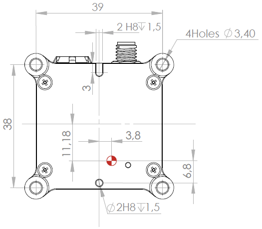
Ellipse-D mechanical outline
All dimensions are in mm.
Ellipse-D Front view
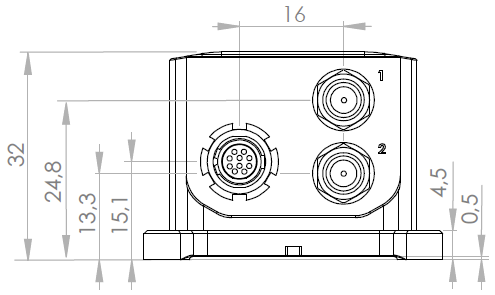
Ellipse-D Top view
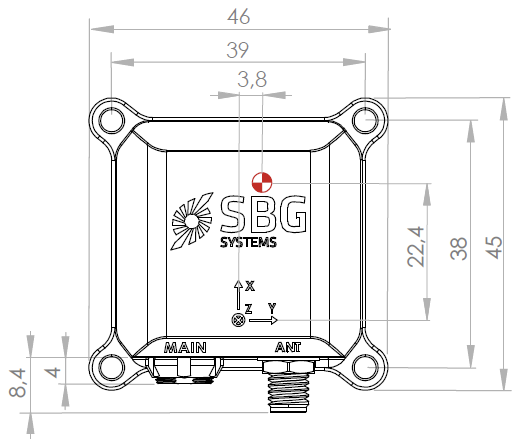
Ellipse-D Right view
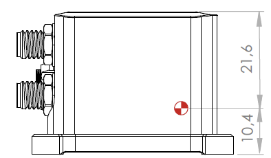
Ellipse-D Bottom view
Equipment mounting
The Ellipse box units can be mounted using 2 locating pins and four M3 screws of minimum length 16 mm.
We recommend A4 alloy or any non-ferromagnetic material when using magnetometers.
Please use an appropriate torque to ensure proper mounting. Units must be mounted on a flat surface.
| Mounting means | Description | Applied force | Quantity |
|---|---|---|---|
| Screws | Socket Cap TCHC DIN 912 M3 x 16mm Stainless Steel A4 | 1.15 N. m | 4 |
| Locating pins | Locating pins MISUMI P/N: SFSSS3-L6,0-+P2,0-B2,0-H5,0-T1,0 SFSSS Serie, 2mm OD x 2mm h 5mm OD x 1 mm h, Shoulder, 3mm OD x 6 mm Length Press Fit Mounting, SS EN1,4301 | N/A | 2 |