Download PDF
Download page Ellipse OEM: Electrical Specifications.
Ellipse OEM: Electrical Specifications
The Ellipse OEM connectors placed:
- On the bottom panel for the main connector
- On the top panel for the antenna connector(s) (Ellipse-N/D only)
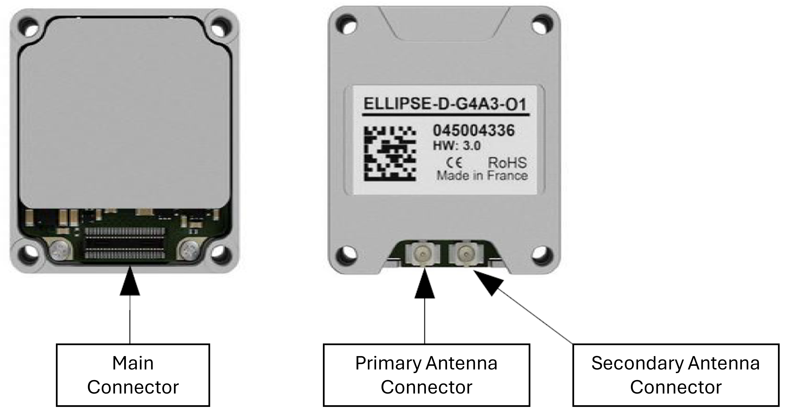
No antenna connectors are available for the A and E versions.
Only the Main Antenna Connector is available for the N version.
Main Connector
The main connector provides access to all Ellipse features using LVTTL signal levels for an easy integration. It provides:
- The main serial port (PORT A) that supports full-duplex communication.
- An additional serial port (PORT E) that supports full-duplex communication.
- One CAN 2.0A/B port that supports up to 1 Mbit/s data rate, to interface with an external CAN transceiver in order to output data on a CAN bus.
- Two multi-function input pins that can be used for:
- Clock synchronization or event marker input pins
- Single or dual channel Odometer input
- Miscellaneous UART input (PORT B) for RTCM data input.
- A synchronization output signal for time stamping and to trigger some equipment.
- A power enable input to turn on and turn off the device.
- An IO power input, separate from the main power input, to adjust the device signal level translation to the host system requirement
Connector specifications
The connector on Ellipse OEM units is placed under the device.
SBG Systems has selected high quality and high density connectors to offer a compact and robust integration.
| Connector | Supplier | Part number | Description |
|---|---|---|---|
| ELLIPSE connector | HIROSE | DF40C-40DP-0.4V(51) | Connector, DF40 Series, Plug/Header, 40 cts, 0.4 mm pitch, SMD |
| Mating connector - option1 | HIROSE | DF40HC(3.0)-40DS-0.4V(51) | Connector, DF40 Series, Receptacle, 40 cts, 0.4 mm pitch, SMD |
Matting connector with other receptacle variants with varying heights are available.
")
The connector used for the Ellipse OEM is not built to receive any mechanical stress. Ensure your mechanical design leaves enough margin for the product to be connected without any stress on the connector.
Connector Pin out for ELLIPSE OEM
| Pin | Signal Name | Type | Description | Connection tips |
|---|---|---|---|---|
| 1 | GND | P | Ground return signal | All ground pins must be connected |
| 2 | GND | P | Ground return signal | All ground pins must be connected |
| 3 | GND | P | Ground return signal | All ground pins must be connected |
| 4 | GND | P | Ground return signal | All ground pins must be connected |
| 5 | VDD | P | Power supply input | All VDD pins must be connected |
| 6 | VDD | P | Power supply input | All VDD pins must be connected |
| 7 | VDD | P | Power supply input | All VDD pins must be connected |
| 8 | VDD | P | Power supply input | All VDD pins must be connected |
| 9 | VDD_IO | P | Power supply input to drive GPIO | Must be connected to VDD for instance |
| 10 | EN | I | Enable input | Must be connected to VDD for instance |
| 11 | PWR_GOOD | I | Power good input (high if good) | Leave unconnected if not used |
| 12 | SYNC_IN_A / ODO_DIR | I | Multi function input. May be used as event input A, or odometer direction | Tie to VDD_IO if not used for better EMC |
| 13 | SYNC_OUT_A | O | Event output A signal | Leave unconnected if not used |
| 14 | SYNC_IN_B / PORTB_RX / ODO | I | Multi function input. May be used as event input B, odometer pulse or Port B Rx line | Tie to VDD_IO if not used for better EMC |
| 15 | CAN_TX | O | Can Tx | Leave unconnected if not used |
| 16 | CAN_RX | I | Can Rx | Tie to VDD_IO if not used for better EMC |
| 17 | PORTA_TX | O | Port A Tx | Leave unconnected if not used |
| 18 | PORTA_RX | I | Port A Rx | Tie to VDD_IO if not used for better EMC |
| 19 | PORTE_TX | O | Port E Tx | Leave unconnected if not used |
| 20 | PORTE_RX | I | Port E Rx | Tie to VDD_IO if not used for better EMC |
| 21 | RESERVED | O | Reserved, do not connect | Leave unconnected |
| 22 | RESERVED | I | Reserved, do not connect | Leave unconnected or tie to GND for better EMC |
| 23 | SYNC_OUT_B | O | Ellipse-A, N, D: No function Ellipse-E: Event output B signal | Leave unconnected if not used |
| 24 | SYNC_IN_C | I | Ellipse-A, N, D: No function Ellipse-E: Event input C signal | Leave unconnected or tie to VDD_IO for better EMC |
| 25 | PORTC_TX | O | Ellipse-A, N, D: No function Ellipse-E: Port C Tx | Leave unconnected |
| 26 | PORTC_RX | I | Ellipse-A, N, D: No function Ellipse-E: Port C Rx | Leave unconnected or tie to VDD_IO for better EMC |
| 27 | RESERVED | O | Reserved, do not connect | Leave unconnected |
| 28 | RESERVED | O | Reserved, do not connect | Leave unconnected |
| 29 | PORTD_TX | O | Ellipse-A, N, D: No function Ellipse-E: Port D Tx | Leave unconnected or tie to VDD_IO for better EMC |
| 30 | PORTD_RX | I | Ellipse-A, N, D: No function Ellipse-E: Port D Rx | Leave unconnected or tie to VDD_IO for better EMC |
| 31 | RESERVED | I | Reserved, do not connect | Leave unconnected or tie to GND for better EMC |
| 32 | SYNC_IN_D | I | Ellipse-A: No function Ellipse-E, N, D: Event input D signal | Leave unconnected or tie to VDD_IO for better EMC |
| 33 | RESERVED | - | Reserved, do not connect | Leave unconnected or tie to GND for better EMC |
| 34 | RESERVED | - | Reserved, do not connect | Leave unconnected or tie to GND for better EMC |
| 35 | RESERVED | - | Reserved, do not connect | Leave unconnected or tie to GND for better EMC |
| 36 | RESERVED | - | Reserved, do not connect | Leave unconnected or tie to GND for better EMC |
| 37 | RESERVED | - | Reserved, do not connect | Leave unconnected or tie to GND for better EMC |
| 38 | RESERVED | - | Reserved, do not connect | Leave unconnected |
| 39 | GND | P | Ground return signal | All ground pins must be connected |
| 40 | GND | P | Ground return signal | All ground pins must be connected |
Pin type P stands for Power Supply either VDD or GND. Other pins are either LVTTL input pins (I) or LVTTL output pins (O)
Electrical specifications for OEM units
Recommended electrical specifications from -40°C to 78°C.
| Item | Conditions | Min | Typical | Max | Unit |
|---|---|---|---|---|---|
| Power supply | |||||
| Input voltage range | 2.5 | 5.5 | V | ||
| Power consumption | Model A – @5V | 250 | mW | ||
| Model E – @5V | 250 | mW | |||
| Model N – @5Vwithout GNSS antenna | 550 | mW | |||
| Model N – @5Vwith GNSS antenna | 600 | mW | |||
| Model D – @ 5V, without GNSS antennas | 800 | mW | |||
| Model D – @ 5V, with GNSS antennas | 900 | mW | |||
| Undervoltage Threshold | Falling Input Voltage | 2.1 | 2.2 | 2.3 | V |
| Recommended Decoupling Capacitance | 2x47 | µF | |||
| VDD_IO | |||||
| Supply Voltage Range | 3.15 (Ellipse-N/D) 1.2 (Ellipse-A/E) | 3.45 (Ellipse-N/D) 3.6 (Ellipse-A/E) | V | ||
| Operating current | 5 | mA | |||
| Recommended Decoupling Capacitance | 1 | µF | |||
| EN | |||||
| Input Voltage Range | 0 | 5.5 | V | ||
| High-Level Threshold Voltage | 1.0 | V | |||
| Low-Level Threshold Voltage | 0.4 | V | |||
| Start Time | Time from EN=High to operational mode | <5 | s | ||
| All other I/Os | |||||
| Input Voltage Range | 0 | 3.6 | V | ||
| High-Level Input Voltage | 1.2V < VDD_IO < 1.95V | VDD_IO x 0.65 | V | ||
| 1.95V < VDD_IO < 2.7V | 1.6 | V | |||
| 2.7V < VDD_IO < 3.6V | 2 | V | |||
| Low-Level Input Voltage | 1.2V < VDD_IO < 1.95V | VDD_IO x 0.35 | V | ||
| 1.95V < VDD_IO < 2.7V | 0.7 | V | |||
| 2.7V < VDD_IO < 3.6V | 0.8 | V | |||
| High or Low Level Output Current | VDD_IO = 1.2V | -3 | +3 | mA | |
| 1.4V < VDD_IO < 1.6V | -6 | +6 | mA | ||
| 1.65V < VDD_IO < 1.95V | -8 | +8 | mA | ||
| 2.3V < VDD_IO < 2.7V | -9 | +9 | mA | ||
| 3.0V < VDD_IO < 3.6V | -12 | +12 | mA | ||
Absolute maximum ratings for OEM units
| Item | Rating |
|---|---|
| All pins to signal GND | -0.3 to 6 V |
| All input pins clamp current | -50 mA |
| All output pins clamp current | 50 mA |
| VDD, EN ESD Rating - Human-body model (HBM), per ANSI/ESDA/JEDEC JS-001 | ±1500 V |
| VDD, EN ESD Rating - Charged-device model (CDM), per JEDEC specification JESD22- C101 | ±500 V |
| VDD_IO & All other IO pins ESD Rating - Human-body model (HBM), per ANSI/ESDA/JEDEC JS-001 | ±8000 V |
VDD_IO & All other IO pins ESD Rating - Charged-device model (CDM), per JEDEC specification JESD22- C101 | ±1000 V |
| RESERVED pins - Human-body model (HBM), per ANSI/ESDA/JEDEC JS-001 | ±1000 V |
| RESERVED pins - Charged-device model (CDM), per ANSI/ESDA/JEDEC JS- 002 | ±250 V |
GNSS antennas connectors for OEM units
To connect an external GNSS antenna the Ellipse-D includes two IP-68 rated SMA connectors. The internal GNSS receiver only supports active GNSS antennas.

Please be advised that the Ellipse doesn't implement any lightning protection. The GNSS antenna and cable are very sensitive to strikes and a proper installation with lightning protection devices may be required.
GNSS antenna advice
The Ellipse-D embeds a high performance GNSS receiver that supports GPS L1/L2, GLONASS G1/G2, Beidou B1/B2, Galileo E1/E5b signals. For best performance and robustness, please follow these recommendations.
| Parameter | Specifications | Remark, conditions |
|---|---|---|
| Antenna connector | u.FL | |
| Input impedance | 50 Ω | |
| LNA supply voltage | 3.0 VDC | |
| LNA supply current | < 30 mA | |
| Maximum Power Input | 10 dBm | Continuous wave, under 50 Ω |
| Minimum antenna gain | 17 dB | |
| Maximum antenna gain | 50 dB |
In order to enable proper measurements, L1/L2 GPS antennas are required, and tracking other constellations is recommended for optimal performance.
SBG Systems has selected some GNSS antennas for different applications. Please refer to the GNSS antennas section to get more details on available antennas.
As a rule of thumb, true heading and/or RTK measurements require high quality GNSS antennas to achieve the stated accuracy.