All dimensions are expressed in millimeters using the International System of Units (SI) conventions.
Overview
The Ellipse OEM units enclosure is made of aluminum surface treated for conductive finish.
The Ellipse OEM uses a high density Hirose DF40 connector. The Ellipse-N and Ellipse-D also includes U.FL standard coaxial connectors to connect the GNSS antennas.
If you are planning to use Ellipse internal magnetometers, please make sure that you don't use ferromagnetic materials to mount the device.
Specifications
The table below summarizes all mechanical and environmental specifications.
| Item | Specification |
|---|
| Size | A, E: 29.5 x 25.5 x 11 mm N, D: 29.5 x 25.5 x 16 mm |
| Weight | A, E: 8 g N, D: 17 g |
| Shocks | Operational: 100g 6ms, half-sine wave Non-operational: 500g 0.1ms, half-sine wave |
| Operating Vibrations | 8g RMS – 20Hz to 2 kHz as per MIL-STD-810G |
| Environmental Specifications |
|---|
| Enclosure | Aluminum, conductive surface finish |
| Operating temperature | -40 to 78°C (-40 to 172.4°F) |
| Storage | -40 to 85°C (-40 to 185°F) |
| MTBF | 218,000 hours MIL-HDBK-217, Ground Mobile |
| Calibration interval | None required, maintenance free |
Origin of measurements
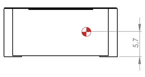
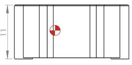
The center of measurement for acceleration, velocity and position is represented on the mechanical outlines by the  symbol. It is referenced to the base plate fine alignment hole.
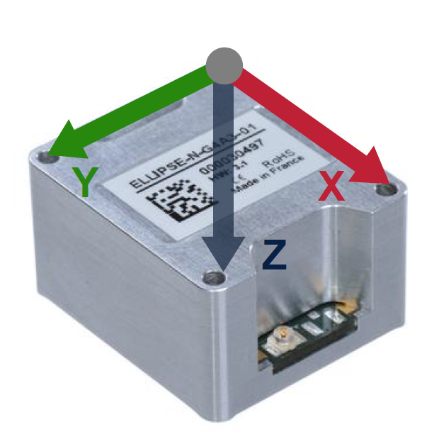
Sensor (body) coordinate frame
This frame is attached to the IMU.
The following diagrams show the body coordinate frame as configured by default. In most situations, the body coordinate frame must be aligned with vehicle coordinate frame. Sensor alignment in vehicle can be rotated by software if the sensor coordinate frame cannot be aligned mechanically.
Check Operating Handbooks for more information on how to configure this alignment using SBG configuration tools.
Mechanical drawings
Ellipse-A OEM and Ellipse-E OEM
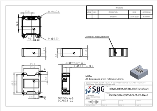
The following document provides the complete mechanical outline and recommendation for the mechanical and mechatronics integration of Ellipse-A OEM and Ellipse-E OEM:
Ellipse-N OEM and Ellipse-D OEM
The following document provides the complete mechanical outline and recommendation for the mechanical and mechatronics integration of Ellipse-N OEM and Ellipse-D OEM:

The diagrams above depict 2u.FL connectors for the Ellipse-D
Please note that only one UFL connector is available for the Ellipse-N OEM version. All dimensions remain the same.
Ellipse-A and E OEM mechanical outline
All dimensions are in mm.
Front View
Back View
Top View
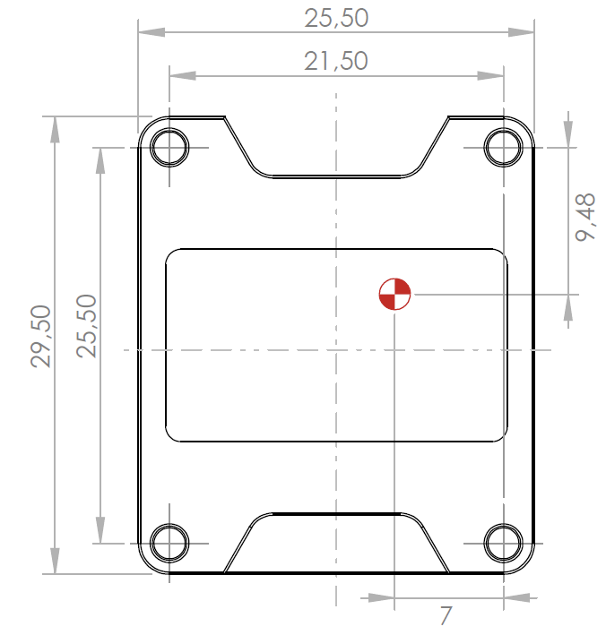
Bottom View
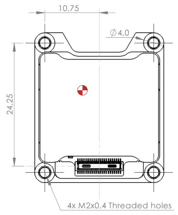
Right View
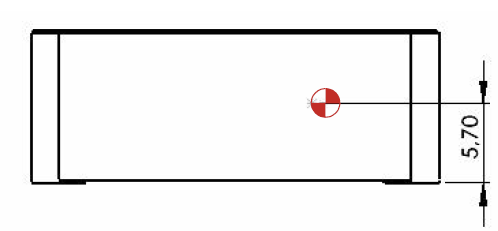
Sectional View
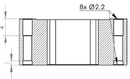
Ellipse-N and D OEM mechanical outline
All dimensions are in mm.
Front View
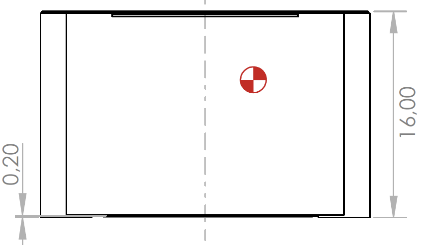
Back View
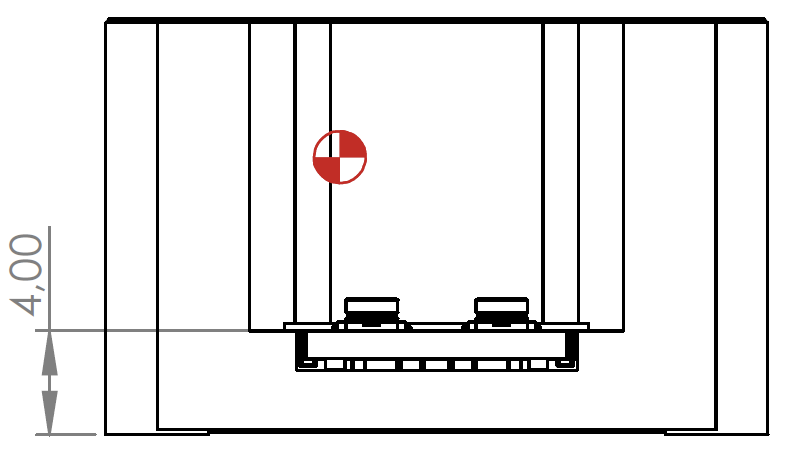
Top View
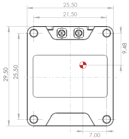
Bottom View
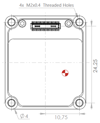
Right View
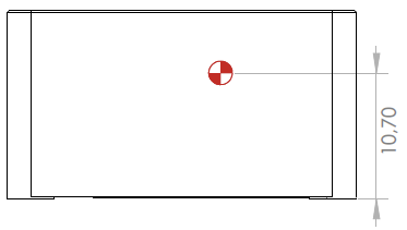
Sectional View
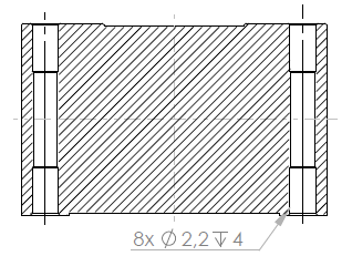
The diagrams above depict 2u.FL connectors for the Ellipse-D
Please note that only one UFL connector is available for the Ellipse-N OEM version. All dimensions remain the same.