Download PDF
Download page DMI integration.
DMI integration
Doc for Ellipse firmware < 3.0
You are currently viewing the documentation for an Ellipse running firmware version v2.x or earlier. If your Ellipse is operating on firmware version ≥ 3.0, please use the version picker in the top-right corner of the page to select the appropriate version.
This operating handbook aims to guide users for Odometer sensor installation and configuration in land applications. This guide is intended for the integration of Odometer systems outputting TTL pulses or CAN information.
Use this document in complement of the Operating Handbook “Use in Land Applications”.
Odometer installation
All our INS models provide an odometer input which can greatly improve performance in challenging environments such as urban canyons.
The odometer provides a reliable velocity information even during GNSS outages. This increases significantly the dead reckoning accuracy.
Our products support:
- Quadrature output or compatible odometers with forward and reverse directions.
- CAN vehicle velocity messages (fully configurable) for setup with direct interface with vehicle’s ODBII connector when using the Ellipse series.
Odometer integration is made really simple as the EKF will finely adjust odometer's gain and will correct residual errors in the odometer alignment and lever arm.
Mechanical Installation
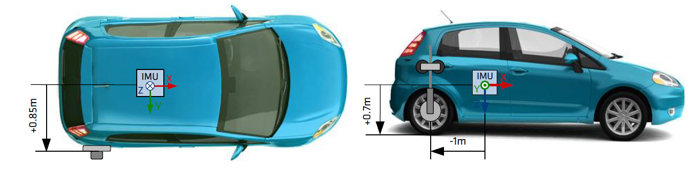
The Odometer has to be placed on a non steering wheel (rear wheel in most applications).
The Odometer lever arm has to be measured. It is the signed distance, expressed in the vehicle coordinate frame, FROM the IMU TO the point of contact between the ground and the tire where the Odometer is installed. It has to be measured with 5cm accuracy.
Electrical installation
SBG Systems INS devices support several DMI (Distance Measurement Instrument) devices and conventions. You can connect simple pulse odometer to more complex quadrature wheel encoders that provide both a velocity and a direction of travel.
For more information, check out the dedicated page.
Pulse Odometer wiring
| Odometer signal | SBG Ellipse INS corresponding signal |
|---|---|
| A | SYNC IN B - PORT B RX - ODOA |
| B | SYNC IN A - ODO B |
| GND | GND |
Can Odometer wiring
| ODB II Connector of CAN bus | SBG Ellipse INS corresponding signal |
|---|---|
| 6 | CAN High |
| 14 | CAN Low |
Software Configuration
Aiding assignment
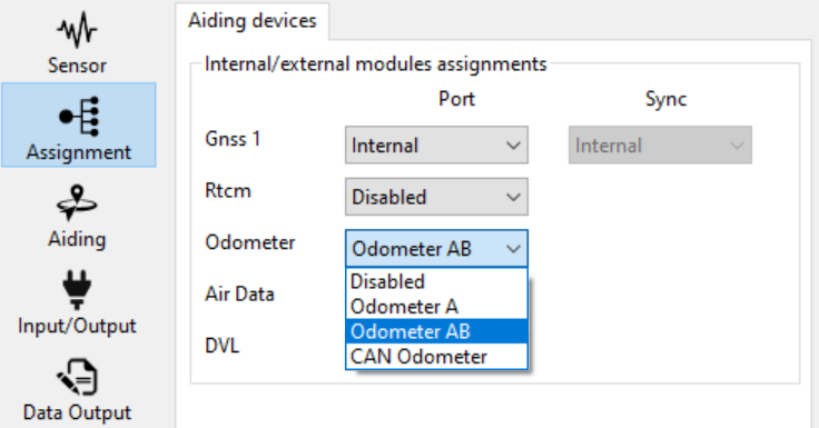
You need enable the odometer in the Assignment tab, by selecting one of the following options:
- Odometer A: Single channel that will only give the distance
- Odometer AB: Dual channels that will give distance and direction
- CAN Odometer: If you can receive velocity over CAN bus (only on B2 version of the Ellipse)
Pulse Odometer configuration
If you are using an odometer and activated it in Aiding Assignments, you will see a thumbnail called “Odometer” in the Aiding panel.
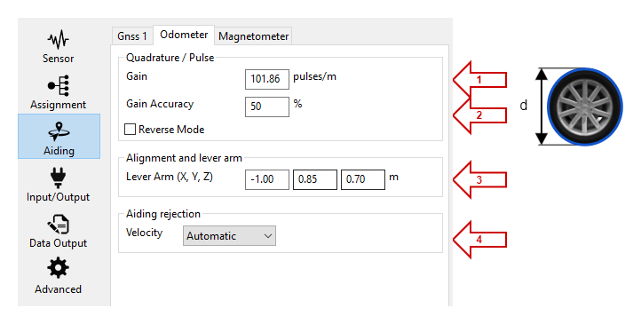
Define here the initial Odometer Gain in pulses per meter.
Gain Accuracy defines how much the Kalman filter needs to estimate the Odometer's gain. Put 100% if you want it to be completely estimated, or 20% if you find your odometer is very accurate. The value of 100 % is recommended in most applications.
Depending on your hardware configuration, the receive mode can be used to reverse the velocity value in order to fit with an actual velocity direction.
Set up here the Odometer lever arm depending on its position from the IMU to the Odometer in the re-aligned INS reference (vehicle reference with X forward, Y to the right, and Z down).
The Aiding rejection Automatic is advised so the Kalman filter determines the confidence of this parameter by itself.
Converting pulses per revolution into pulses per meter
Your odometer might specify a number of pulses per revolution. To convert that value into the expected gain in pulses per meter, you need to convert as follow:

With P being the number of pulses per revolutions, d being the diameter of the wheel
Example with a 128 pulses per revolution odometer on a 40 cm diameter wheel
Gain = 128 / (π x 0.4) = 101.86 pulses/m
CAN Odometer configuration
In case a CAN odometer has been selected, the velocity and direction can be read from the CAN bus of the car, connected to the unit by the ODB connector.
You need to open first the can bus with the right bitrate in the Input/Output tab. If you are using the can bus just to receive odometer information set it in “Listen only mode”.
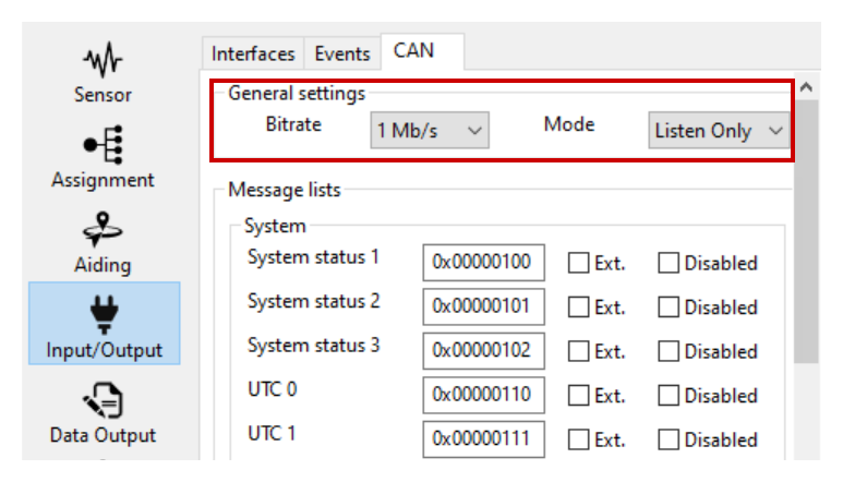
Then you need to configure the source message to get the velocity and eventually direction information in the Aiding Tab in the CAN section.
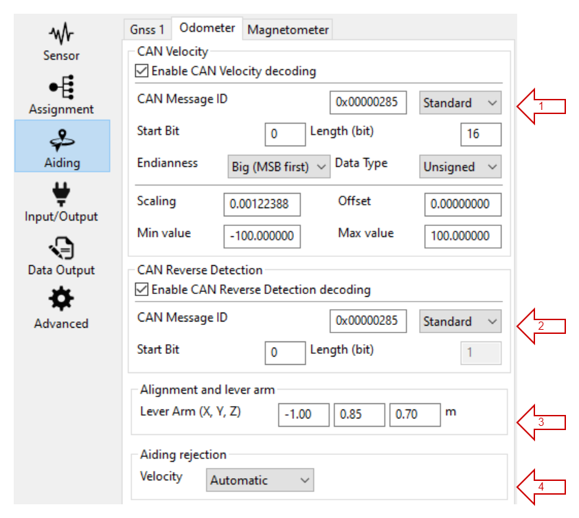
- You need to know the ID of the velocity message and select it in the configuration, then also enter the messages details such as the Start bit and the length of the relevant information from the CAN message. These data are usually available in a DBC file that can be provided by the car manufacturer.
- If available you may also select one bit from a message that states the direction. It is recommended to configure it, especially if the car will have backward moves.
Set up here the Odometer lever arm depending on its position from the IMU to the Odometer in the re-aligned INS reference (vehicle reference with X forward, Y to the right, and Z down).
The Aiding rejection Automatic is advised so the Kalman filter determines the confidence of this parameter by itself.
Data Output
For data check, make sure you output the Odometer on “New Data” :
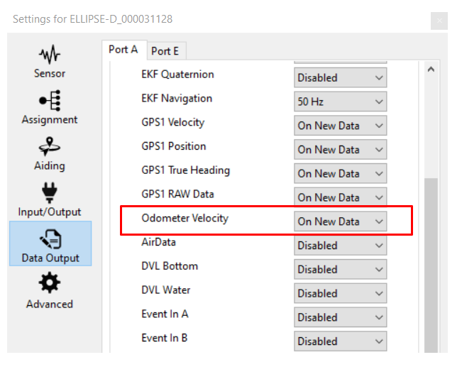
This is not mandatory for Odometer use, but will allow to check the data received from the Odometer in the sbgCenter.
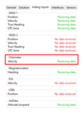
Data checking
You can check the Odometer data directly in the sbgCenter by looking at the Aiding Status:
Note: This status will only be green when there is a speed measured, so when the vehicle is on motion.
You can also check the Odometer data directly in the sbgCenter, and compare it to GNSS velocity to track for any gain configuration error.
