Download PDF
Download page External Septentrio GNSS.
External Septentrio GNSS
This brief document guides you in the process of configuring an external Septentrio GNSS receiver for your Ellipse INS products.
Use this document in complement of the Operating Handbooks.
Step 1: GNSS and Ellipse connections
Connect GNSS Tx signal(s) pin to the Rx pin on one of the following Ellipse connectors: PORT A, B, C, D or E. Please also connect Ellipse and GNSS ground signals to each other.
Connect GNSS PPS signal pin to Sync A, B, C or D input pin.
Step 2: GNSS module configuration
Septentrio configuration can be performed using RxControl, or the embedded web interface.
Basic operation
Configure the following outputs and output rates on your GNSS receiver:
PVTGeodetic @ 5 Hz
PosCovGeodetic @ 5 Hz
VelCovGeodetic @ 5 Hz
AttEuler @ 5 Hz (if applicable, on dual antenna systems)
AttCovEuler @ 5 Hz (if applicable, on dual antenna systems)
ReceiverTime @ 1Hz
AuxAntPosition @ 1Hz
xPPSOffset @ 1Hz
PPS signal
For proper operation, a PPS signal must be provided at 1 Hz. Please configure the Septentrio receiver to output a PPS signal at 1 Hz on a rising edge (Low2High).
Septentrio PPS signal strength is usually weak (3V pulse). If the PPS cable is too long or split, this signal may require pre‑amplification using third party hardware to work properly.
Adding post-processing capability
The output set “PostProcess” must be enabled at 1Hz as well for post-processing operation, It contains the following output:
MeasEpoch, MeasExtra @ 1Hz
GEORawL1 @ 1Hz
GPSNav, GPSIon, GPSUtc @ 1Hz
GLONav, GLOTime @ 1Hz
GALNav, GALIon, GALUtc, GALGstGps, GALSARRLM @1 Hz
BDSNav @ 1Hz
QZSNav @ 1Hz
DiffCorrIn @ 1Hz
ReceiverSetup @ 1Hz
Commands @ 1Hz
Other GNSS Configuration
Datum is set to WGS84.
Receiver dynamics should be set to:
Acceleration / Jerk: High
Motion: Unlimited
Smoothing options must be disabled
Step 3: Sensor configuration
In order to configure the Ellipse-E, you need to use the sbgCenter and open the configuration window. Simply follow those instructions:
Set aiding assignment
In this window, you just indicate where you connected your GNSS receiver.
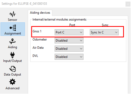
Both communication port and Sync In pin must be set.
Set correct baud rate and mode for serial port
In our example we configured the GNSS to be connected on PORT C in RS‑232 mode using a baudrate of 460800 bauds.
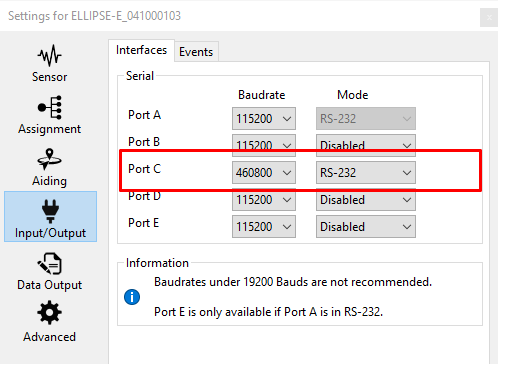
Post Processing messages contain a lot of packets, sufficient baudrate speed should be then selected. We recommend a speed of 460800 bauds in that case.
Set logic input configuration for PPS signal
In order to use correctly PPS signal information, you must enable the corresponding logic input. Here we configured PPS on Sync C.
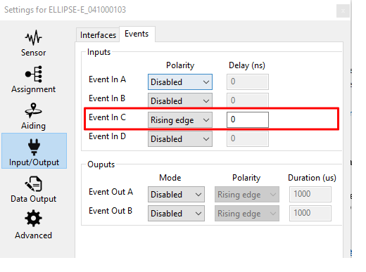
Polarity should be set accordingly with the actual PPS signal (rising edge or falling edge).
Set correct GNSS model and configuration
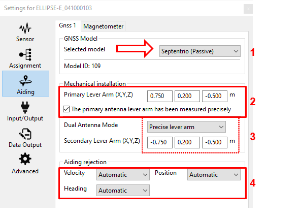
GNSS model should be set to Septentrio (Passive).
GNSS lever arms are to be measured with 5 cm accuracy FROM the IMU TO the antenna phase center (APC), in the vehicle frame. If the option “The primary antenna lever arm has been measured precisely” is ticked, then the Extended Kalman filter will take these values for granted and will not estimate any values for this Primary antenna lever arm. It should help the system to align faster, but in this case, the Primary antenna lever arms must be measured within 1 cm accuracy.
In case of Dual antenna system, the secondary antenna lever arm must also be entered FROM the IMU TO the antenna phase center (APC), and the same accuracy requirements as for the primary antenna apply, depending if the above selection box is set to "Precise" or "Rough" lever arm value.
Finally, each available measurement (position, velocity, and heading if available i.e. if using a dual antenna receiver) should be configured to be used or not. Automatic is recommended.
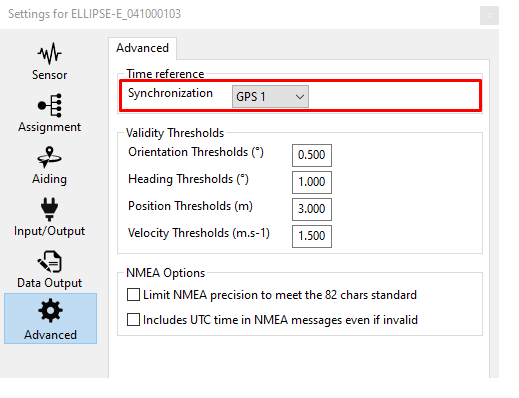
Check clock alignment
Finally, you check that the time synchronization reference is set to GPS 1 (default configuration).
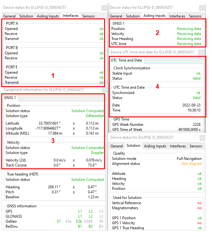
Step 4: Checking status
The status and GNSS windows should be checked carefully before going further. These status indicators will give essential hints in case of troubles to get a correct fix. Each step is labeled in red in the following screenshot.
Corresponding COM port must be OK.
GNSS 1 frame in “Aiding Inputs” tab must show that the data is received. Not seeing this would probably imply that there is a baudrate or wiring issue.
After that, you can check if the GNSS solution has been calculated and is consistent.
Then you can check the "Clock" section. Input clock must be OK and UTC time should be set to valid after a few minutes in steering mode.