Download PDF
Download page Ellipse Boxed: Electrical Specifications.
Ellipse Boxed: Electrical Specifications
The Ellipse connectors are all placed on the front panel. The connectors are referenced and identified by laser marking on the enclosure.
SBG Systems has selected high quality connectors designed for harsh environments. They offer an IP-68 protection when the plug is properly mounted.
The Ellipse development kit cables are not designed to offer an IP-68 protection. Contact SBG Systems to get further support about IP-68 protection.
Overview of the connectors
Ellipse-A: AHRS without GNSS aiding
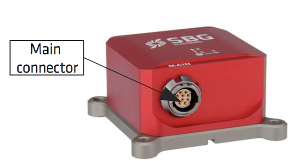
Ellipse-E: INS with external GNSS aiding only
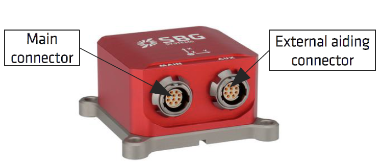
Ellipse-N: INS with embedded single antenna GNSS receiver
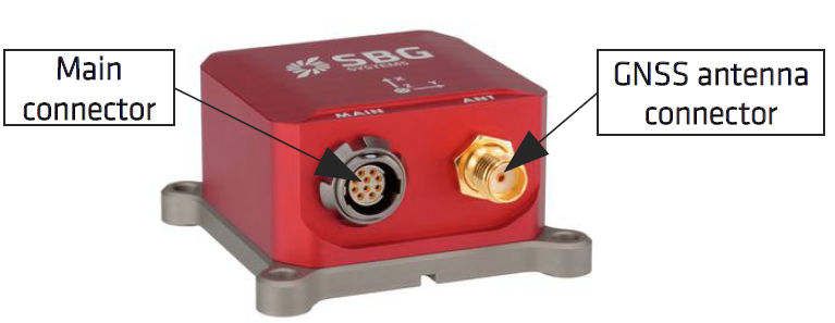
Ellipse-D: INS with embedded dual antenna GNSS receiver
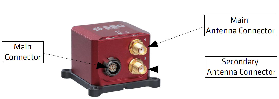
Main connector (Ellipse-A / Ellipse-E / Ellipse-N / Ellipse-D)
The main connector provides access to most Ellipse features in a modular way. It provides:
- The main serial port (PORT A) that supports full-duplex communication. It operates in RS-232, or alternatively in RS-422 on B1 devices by pulling down to GND the pin 5.
- An optional RS-232 port (PORT E) that can be enabled on non-CAN versions of the Ellipse, when PORT A is configured in RS-232 mode.
- One CAN 2.0A/B connection that supports up to 1 Mbit/s data rate used to output data – only avaiable on CAN versions on the Ellipse.
- Two multi-function input pins that can be used for:
- Clock synchronization or event marker input pins.
- Single or dual channel Odometer input.
- Miscellaneous RS-232 input (PORT B) for RTCM data input on Ellipse-N and Ellipse-D.
- A Synchronization output signal for time stamping and to trigger some equipment.
Connector specifications
The connector on Ellipse box units is placed on the front panel. The connector is referenced and identified by laser marking on the enclosure.
SBG Systems has selected high quality connectors designed for harsh environments. They offer an IP-68 protection rating when the plug is properly mounted.
| Connector | Manufacturer | Part number | Description |
|---|---|---|---|
| ELLIPSE Box I/O connectors | Fischer Connectors | UR02W07 F010P BK1 E2AB | Connector, UltiMate Serie, Receptacle, Sockets, 10 cts |
| Mating connector | Fischer Connectors | UP01L07 M010S BK1 Z2ZB | Connector, UltiMate Serie, Plug, Pins, 10 cts |
The mating connector doesn't include the cable clamp sets. Other plugs with right angle or other options may be found if required.
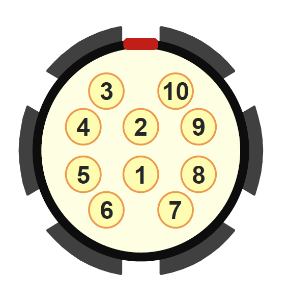
Connector pin out for Ellipse B1 (non-CAN) versions
The following pinout is applicable for all non-CAN versions of the Ellipse.
| Pin # | Signal Name | Description |
|---|---|---|
| 1 | SYNC IN A - ODO B | Multi function input. May be used as clock/event, or odometer input |
| 2 | SYNC IN B – PORT B RX - ODO A | Multi function input. May be used as clock/event, odometer input, or RS-232 Rx line |
| 3 | VIN | Power supply input |
| 4 | GND | Ground return signal |
| 5 | PORT A RS-232/ RS-422 | Port A RS-232 or RS-422 selector. Tie to GND to select RS-422 |
| 6 | SYNC OUT A | Synchronization output signal. |
| 7 | PORT E TX – PORT A RS422 TX+ | Port E Tx line, or Port A Tx+ in RS-422 mode |
| 8 | PORT A RS232 TX – PORT A RS422 TX- | Port A RS-422 Tx- or RS-232 Tx line |
| 9 | PORT A RS232 RX – PORT A RS422 RX+ | Port A RS-422 Rx+ or RS-232 Rx line |
| 10 | PORT E RX – PORT A RS422 RX- | Port E Rx line, or Port A Rx- in RS-422 mode |
By default, if you leave the RS-232/RS-422 signal unconnected, the Port A will operate in RS-232 mode.
Connector pin out for Ellipse B2 (CAN) versions
The following pinout is applicable for all CAN versions of the Ellipse.
| Pin # | Signal Name | Description |
|---|---|---|
| 1 | SYNC IN A - ODO B | Multi function input. May be used as clock/event, or odometer input |
| 2 | SYNC IN B – PORT B RX - ODO A | Multi function input. May be used as clock/event, odometer input, or RS-232 Rx line for RTCM correction input |
| 3 | VIN | Power supply input |
| 4 | GND | Ground return signal |
| 5 | NC | Not used. Leave unconnected. |
| 6 | SYNC OUT A | Synchronization output signal. |
| 7 | CAN L | CAN Low |
| 8 | PORT A RS232 TX | Port A RS-232 Tx line |
| 9 | PORT A RS232 RX | Port A RS-232 Rx line |
| 10 | CAN H | CAN High |
CAN versions and RS422
Keep in mind that CAN versions of the Ellipse do not support RS422 on the main connector.
If you need RS422 connectivity, you can either: use an Ellipse-E CAN ; or use an Ellipse-A/N/D without CAN.
Auxiliary connector (Ellipse-E)
The Ellipse-E includes an additional connector. It is mainly used to connect aiding equipment to the Ellipse-E. It features the following connections:
- A full duplex RS-232 / RS-422 port for GNSS aiding connection (PORT C).
- An additional RS-232 input for upward compatibility (PORT D).
- Two synchronization input signals used for internal clock synchronization, data time stamping and/or event markers.
- A Synchronization output signal for time stamping and to trigger some equipment.
Connector specifications
Please refer to the section above (Main connector) for more details, as the same connector type is used for Main and Aux connectors.
Connector pin-out
| Pin # | Signal Name | Description |
|---|---|---|
| 1 | SYNC IN C | May be used as clock/event input |
| 2 | SYNC IN D | May be used as clock/event input |
| 3 | PORT D RX | RS-232 input for miscellaneous applications |
| 4 | GND | Ground return signal |
| 5 | NC | Not internally connected |
| 6 | SYNC OUT B | Synchronization output signal |
| 7 | PORT C RS422 TX+ | Port C RS-422 Tx+. Not used in RS-232 connection |
| 8 | PORT C RS232 TX – PORT C RS422 TX- | Port C RS-422 Tx- or RS-232 Tx line |
| 9 | PORT C RS232 RX – PORT C RS422 RX+ | Port C RS-422 Rx+ or RS-232 Rx line |
| 10 | PORT C RS422 RX- | Port C RS-422 Rx-. Not used in RS-232 connection. |
Electrical specifications for BOX units
Recommended electrical specifications from -40°C to 85°C.
| Item | Conditions | Min | Typical | Max | Unit |
|---|---|---|---|---|---|
| Power supply | |||||
| Input voltage range | 5 | 36 | V | ||
| Power consumption | Model A – @12V | 300 | mW | ||
| Model E – @12V | 325 | mW | |||
| Model N – @12V without GNSS antenna | 600 | mW | |||
| Model N – @12V with GNSS antenna | 750 | mW | |||
| Model D – @ 12V, without GNSS antennas | 900 | mW | |||
| Model D – @ 12V, with GNSS antennas | 1050 | mW | |||
| RS-232 Receivers, Sync In pins | |||||
| Input range | -15 | 15 | V | ||
| Low level threshold | 0.6 | V | |||
| High level threshold | 2.0 | V | |||
| Input resistance | 3 | 5 | 7 | kΩ | |
| RS-422 Receivers | |||||
| Input differential threshold | -200 | -125 | -50 | mV | |
| Input hysteresis | 25 | mV | |||
| Input resistance | 96 | kΩ | |||
| RS-232 Transmitters | |||||
| Output range | +/- 5 | +/- 5.5 | V | ||
| RS-422 transmitters | |||||
| Differential output voltage | 2 | V | |||
| Common mode output voltage | 3 | V | |||
| Sync Out pins | |||||
| High Level Output voltage | ILoad < 100μA ILoad < 16mA | 3.2 2.6 | V V | ||
| Low Level Output voltage | ILoad < 100μA ILoad < 16mA | 0.1 0.4 | V V | ||
| CAN bus | |||||
| Recessive Bus Voltage | 2 | 2.5 | 3 | V | |
| CAN H Output Voltage | dominant | 2.75 | 3.5 | 4.5 | V |
| CAN L Output Voltage | dominant | 0.5 | 1.25 | 2.25 | V |
| Absolute input voltage | CANH, CANL | -58 | 58 | V | |
| Differential input voltage | CANH, CANL | 0.5 | 0.7 | 0.9 | V |
Absolute maximum ratings for BOX units
| Item | Rating |
|---|---|
| VDD - GND | -36 to 36 V |
| Rx+, Rx-, Logic inputs pins input voltage to signal GND | ±18V |
| Logic output Max current | 50 mA |
| CANH, CANL | ±80 V |
| ESD protection (Tx, Rx, Input & Output pins, CANH, CANL) | 15 kV |
GNSS antennas connectors for BOX units (Ellipse-N and D)
To connect an external GNSS antenna the Ellipse-D includes two IP-68 rated SMA connectors. The internal GNSS receiver only supports active GNSS antennas.
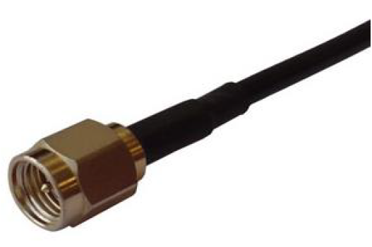
Please be advised that the Ellipse doesn't implement any lightning protection. The GNSS antenna and cable are very sensitive to strikes and a proper installation with lightning protection devices may be required.
For best performance, the antenna(s) should be connected before the power is applied. The Ellipse GNSS estimates the noise floor of the antenna during the startup sequence.
GNSS antenna advice
The Ellipse-N and Ellipse-D embed a high performance GNSS receiver that supports GPS L1/L2, GLONASS G1/G2, Beidou B1/B2, Galileo E1/E5b signals. For best performance and robustness, please follow these recommendations.
| Parameter | Specifications | Remark, conditions |
|---|---|---|
| Antenna connector | SMA female | IP-68 when connected |
| Input impedance | 50 Ω | |
| LNA supply voltage | 3.0 VDC | |
| LNA supply current | < 30 mA | |
| Maximum Power Input | 10 dBm | Continuous wave, under 50 Ω |
| Minimum antenna gain | 17 dB | |
| Maximum antenna gain | 50 dB |
In order to enable proper measurements, L1/L2 GPS antennas are required, and tracking other constellations is recommended for optimal performance.
SBG Systems has selected some GNSS antennas for different applications. Please refer to the GNSS antennas section to get more details on available antennas.
As a rule of thumb, true heading and/or RTK measurements require high quality GNSS antennas to achieve the stated accuracy.