Download PDF
Download page DVL integration.
DVL integration
Doc for Ellipse firmware ≥ 3.0
You are currently viewing the documentation for an Ellipse running firmware version ≥ 3.0. If your Ellipse is operating on firmware version 2.x or earlier, please use the version picker in the top-right corner of the page to select the appropriate version.
This operating handbook aims to guide users for DVL sensor installation and configuration in marine environment. This guide is intended for the integration of any DVL systems outputting Teledyne PD6, Wayfinder or Nortek DVL-1000, Nucleus messages.
Use this document in complement of the Operating Handbook “Marine applications”.
Mechanical installation
The DVL must be rigidly fixed to the vessel structure.
It is recommended to align the DVL forward mark toward the vessel bow.
For a right-handed frame DVL (NED)
The settings are straight forward, you just need to report the misalignment angles from vehicle reference frame

The axis alignement is X-Forward, Y-Right (Z-Down) and alignment angle to enter in the inertial system configuration is Roll=0°, Pitch=0°, Yaw=0°.
For a Left-handed frame DVL (ENU)
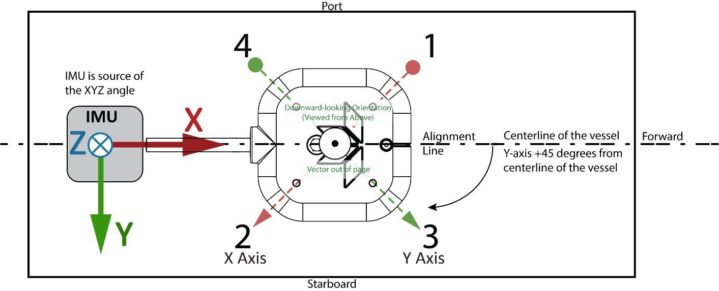
The axis alignement is X-Backward, Y-Right (Z-UP) and the alignment angle to enter in the inertial system configuration is Roll=0°, Pitch=0°, Yaw=-45°
Electrical connections
The typical DVL electrical integration takes care of two main aspects:
- The DVL data output
- Synchronization between DVL and INS
Data output connection
Regarding the data output, a simple serial connection is generally used, by connecting the DVL serial port to one of the SBG INS available serial ports (eg. PORT A Rx), either in RS-232 or in RS-422.
Synchronization between DVL and SBG INS
DVL Master
In this mode of operation, the DVL runs on its own and can send a synchronization pulse to the SBG INS whenever a new velocity measurement is available.
The measurement rate might be not constant depending on water conditions.
To operate in this mode, the DVL synchronization output must be connected to one of the available SBG INS SYNC IN pins.
DVL Slave
In this mode of operation, the SBG INS generates a regular pulse signal to trigger each measurements of the DVL.
The measurement rate can be constant in this mode, driven by the SBG INS SYNC OUT rate.
However care must be taken in setting up the SYNC OUT Rate to mach the minimum DVL's timing requirement, based on DVL type, configuration, and maximum depth during the mission.
In other words, the DVL must be able to send a ultrasonic pulse, wait for the echo and process the data before the next trigger shall occur.
Setting the right rate
SBG Systems recommends you to contact your DVL's manufacturer to know what allowable SYNC OUT rates can be used depending on your system configuration and water environment.
As a rule of thumb, an update rate between 1Hz and 10Hz is feasible in shallow water conditions.
Software configuration
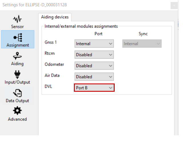
Assignment
Select the DVL on the input port of your choice (for instance in this case Port B).
Aiding
In Aiding tab we select the frames model, position and orientation, then rejection of the DVL.
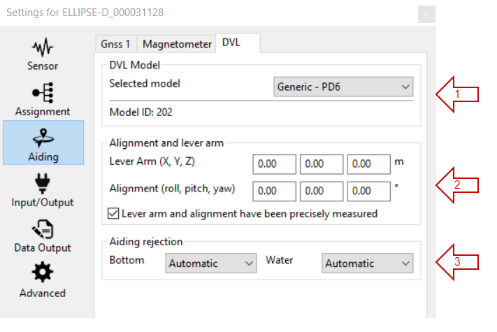
Select the communication protocol : Teledyne PD6, Wayfinder or Nortek DVL-1000, Nucleus.
Then select:
the lever arm: from the IMU to the DVL position in the re-aligned INS reference (vehicle reference with X forward, Y to the right, and Z down).
- The orientation of the DVL. The orientation should be left to zero in DVL software to be entered here.
- If the accuracy box is checked, the filter will trust the values entered for orientation and lever arms and will not try to re-estimate them during operation which will speed-up the alignment phase (but make this choice only if accurate within 1 cm for lever arms, and better than 1 degree for orientation).
- The Aiding rejection: Automatic is advised for both Bottom and Water, so the Kalman filter determines the confidence of this parameter by itself.
PD6
When using the PD6 format, the following PD6 frames are required: SA, TS, WI, WD, BI, BD.
Input / Output
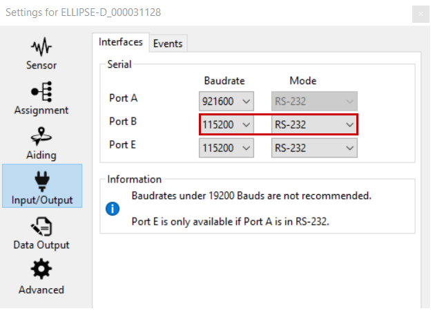
Interfaces
Configure the baudrate of the serial port to be the same as on the DVL on configuration (in this example we assume the DVL was set in 112500 bps baudrate using RS-422).
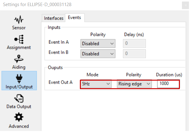
Events
Configure the synchronization input or output, making sure it matches the DVL polarity and timing requirements. Our example shows that we use an update rate of 5Hz.
Data Output
For data check, make sure you output the DVL Bottom Track and DVL Water Layer on “New Data” :
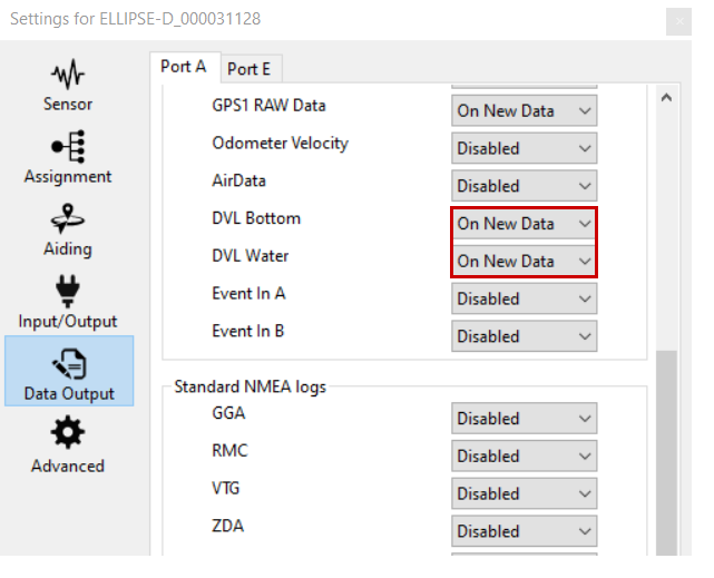
This is not mandatory for DVL use, but will allow to check the data received from the DVL in the sbgCenter for monitoring purpose.
Operation
Data check
You can also check the DVL data directly in the sbgCenter: Please note the velocities will be directly the ones from the DVL, so no orientation compensation will be applied (it is only applied internally by the Kalman filter).
In the following example, we got a velocity on the X and Y axes because the DVL was installed with a 45° angle.
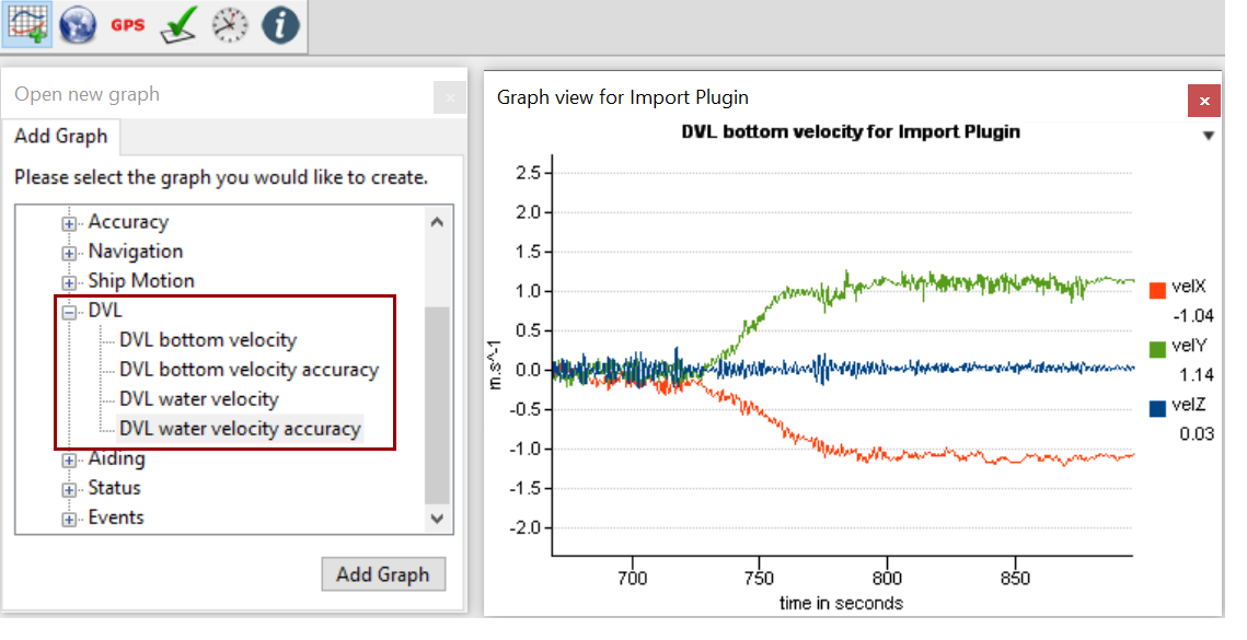
This requires that you output the DVL Bottom Track and DVL Water Layer in the Data Output section.
DVL Calibration
At each start, the DVL will be automatically calibrated by the INS over time if the check box was not checked in Aiding Settings, and adjust your DVL installation parameters, as well as DVL's scale factor. This requires:
- Good GNSS reception: To Initialize and warm-up the INS and be used as a reference for DVL alignment and gain estimations.
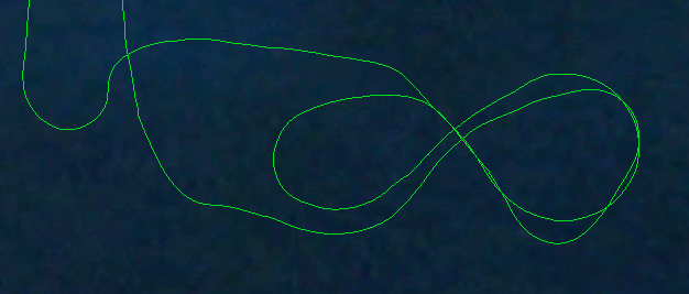
- Dynamic motion : DVL calibration parameters need some dynamic maneuvers to be "observed" and refined by the Kalman filter.
A typical alignment pattern is shown in the next picture :