Download PDF
Download page LiDAR integration with an Ellipse.
LiDAR integration with an Ellipse
Introduction
Integrating a LiDAR sensor with an Ellipse inertial navigation system enables precise georeferencing of point clouds by combining accurate positioning, orientation, and timing information.
This type of integration is commonly used in applications such as: UAV surveying, robotics, and autonomous navigation.
This article provides a step-by-step guide to successfully integrate a LiDAR with an Ellipse device. It covers the key concepts, hardware connections, time synchronization strategies, and software configuration required to ensure reliable and accurate LiDAR georeferencing. We'll use the Ellipse-D and a Ouster Lidar in this guide as an example.
Mechanical installation
Please consider the following recommendations:
- The INS and the LiDAR should be rigidly fixed on the same support.
- The INS should be static in regard to antenna(s) and LiDAR.
- The LiDAR and the INS should be close to each other to avoid boresight angles instability.
- The INS should be far from strong vibration sources.
- Keep the antenna(s) as far apart as possible from the LiDAR to prevent signal interference generated by many devices on the market.
- The LiDAR placement and orientation should be optimized to maximize the distance covered and the resolution.
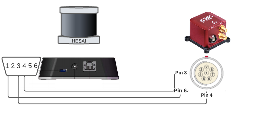
| Lidar | INS |
|---|---|
| Pin #1: PPS (pulse-per-second) signal for synchronization | Pin #6: SYNC OUT-A Synchronization output signal |
| Pin #3 or #5: GND for the external GNSS module | Pin #4: GND |
| Pin #4: Receiving serial data from the external GPS module | Pin #4: PORT A RS232 Tx |
SBG Systems IMU are designed to handle vibrations without specific care. Nevertheless in case of highly vibrating environment, a mechanical vibration isolation might be required for proper operation and optimal LiDAR data quality. Properly sized silicon or wire dampers can be used for that purpose.
Ellipse configuration
Using SBGCenter
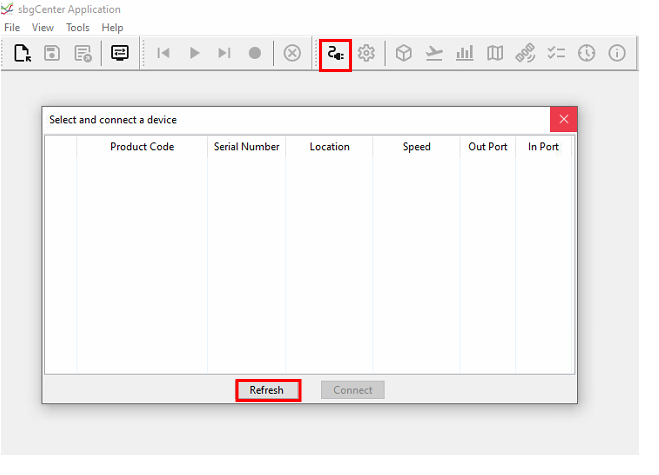
Click on the connect icon, then on refresh to search all the units connected.
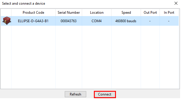
Select the unit and click on connect.
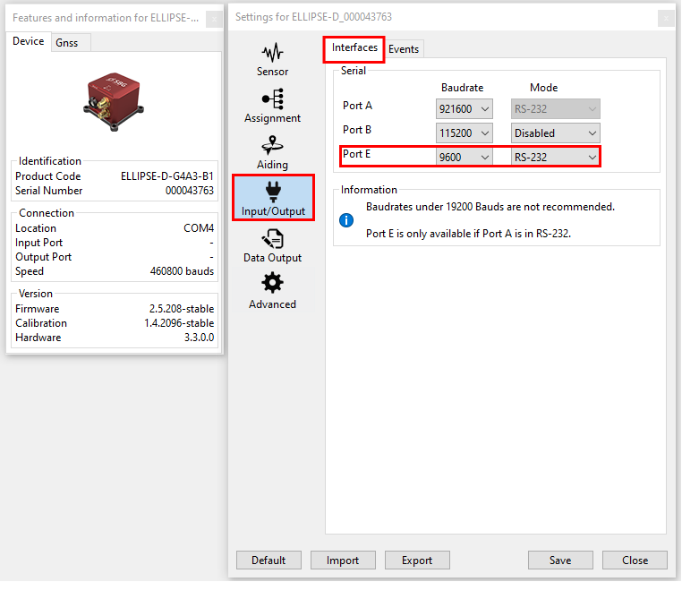
Input/Output configuration
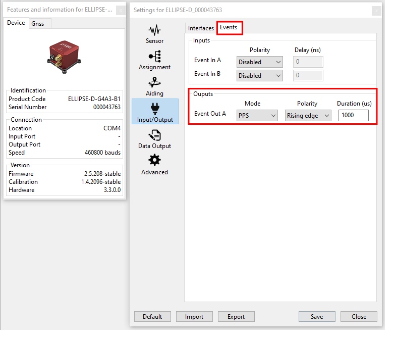
Here we will configure the port E from the serial interface to output messages at baudrate of 9600, but another port could be used if needed, and another baudrate too, as long as it's the same on the lidar side. We'll also configure Event out A, to output 1PPS, to synchronise the lidar.
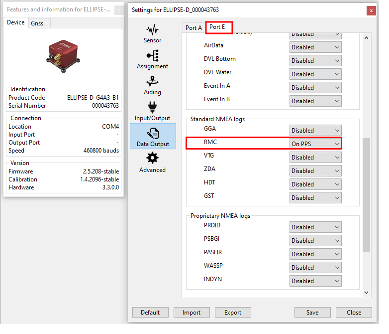
Data output configuration
We will configure a NMEA standard RMC output sentence that will provide position and time to the Ouster. The output rate must be set to on PPS.
Using RestAPI
It is possible to configure Ellipse from the command line since firmware 3, from sbgECom library.
For more details on how to configure an Ellipse using RestAPI, please refer to Configuration API (sbgInsRestApi)
Ouster configuration
Connect to the product
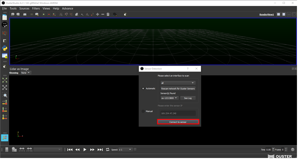
For that, please download OusterStudio in case you're using Ouster. For other models, you will find the equivalent (Veloview for Velodyne, Pandar for Hesai, ...).
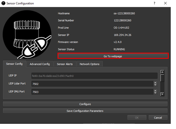
Open the interface and connect the unit, automatically, by scanning all the sensors in your network. Or manually by insering the IP adress, if it's fix and you know it. Then, click on Connect to sensor.
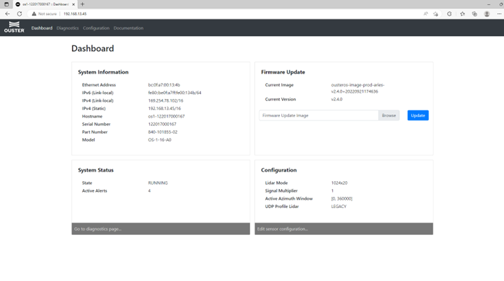
Then, on sensor configuration, you can decide to configure it on OusterStudio or, click on Go To webpage. And if you want to have access to the webpage, you can also use the hostname or the IP adress on the web browser.
Configuration
General configuration
Network and mode configuration won't be discussed in this article.
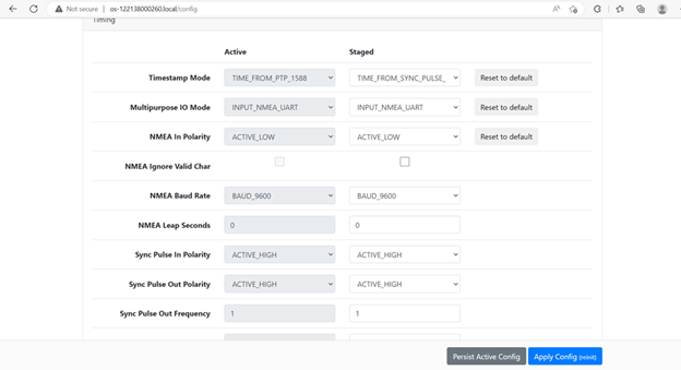
So, in timing configuration, please set NMEA_INPUT_POLARITY to ACTIVE_LOW. NMEA input baud rate to 9600.
PPS synchro should be set to ACTIVE_HIGH.