Download PDF
Download page Receive RTK corrections via NTRIP using ArduSimple.
Receive RTK corrections via NTRIP using ArduSimple
Our Ellipse INS with built-in GNSS receivers (Ellipse-N and Ellipse-D) are all compatible with RTK, however, since they do not embed internet connectivity, the corrections need to be sent over serial with an external equipment. The ArduSimple 4G NTRIP Master is an example of such an equipment.
This article gives the instructions concerning the configuration of ArduSimple board for receiving RTK corrections via NTRIP and sending them to the Ellipse, but any other Modem/NTRIP client could be used.
Configuration on the ArduSimple Side
Equipment
The ArduSimple needed boards are:
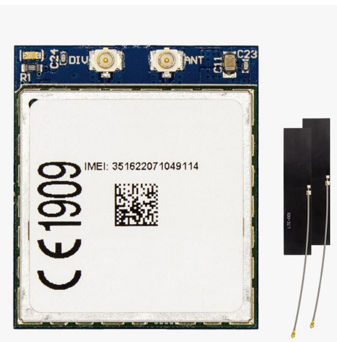
ArduSimple 4G NTRIP Master : this board is provided with two uFL radio antennas
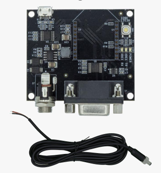
- RS232 Carrier Board for XBee Plugins: This board allows you to convert any XBee-compatible device into an RS232 device.
Power supply information
The power supply of this board depends on the used port:
- USB port: 4.5V - 5.5V
- Jack port: 4.5V - 16V
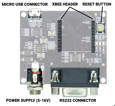
The functionnal view of this board is as follows:
Hardware setup
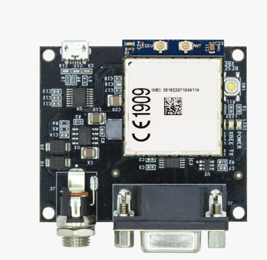
The 4G NTRIP Master board has to be installed on the RS232 Carrier Board for XBee Plugins as shown below:
Software configuration
Warning
Do not insert yet micro-SIM card inside 4G NTRIP Master. SIM card must be introduced only after loading the 'Parameters file'.
1- Use form on website at Ardusimple Master Hookup Guide to generate 'Parameters file'. This file requires as a minimum the following:
- SIM PIN
- APN name (internet provider)
- NTRIP caster settings
2- Plug 4G NTRIP Master on the XBEE header of the RS232 Carrier Board for XBee Plugins
3- Connect uFL radio antennas to 4G NTRIP Master
4- Power up RS232 Carrier Board for XBee Plugins
5- Download and install 4G NTRIP Master Configuration Tool available on the same website address Ardusimple Master Hookup Guide
6- Launch 4G NTRIP Master Configuration Tool and connect to COM(POWER+XBEE)
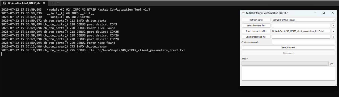
7- Load Parameters file (as shown in the following picture):
8- Click on 'Send/Connect' to transfer settings from Parameters file to 4G NTRIP Master
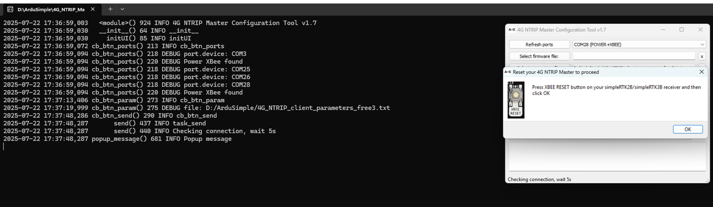
9- Press 4G NTRIP Master reset button and click on 'OK' to start setting upload
10- Once 'Parameters file' loaded, power down RS232 Carrier Board for XBee Plugins
11- Insert micro-SIM card inside 4G NTRIP Master
12- Power up RS232 Carrier Board for XBee Plugins
13- Connect RS232 Carrier Board for XBee Plugins COM port to GNSS receiver expecting NTRIP corrections
Status LED
The status led indicates the state of the board:
OFF: device OFF or in firmware upgrade mode
ON: boot
Fast blink (5 blinks/second): all good! device in run mode
Slow blink (1 blink/second): device in command mode
Fast+slow blink (irregular blink): modem is trying to connect to network.
This status should last a few seconds only in normal operation.
If this status remain active for long period, it means that the modem can’t connect to the network, it could be for several reasons (wrong APN, modem antennas not connected, bad cellular network coverage, …)
Ellipse side
Hardware setup
The RTK corrections can be sent via the serial port of the Ellipse with the use of this cables : CA-ELI-SPLIT-RS232-DB-0.5M.
You can also design your custom harness using your own wires, or the open wire provided by SBG Systems.
Software configuration
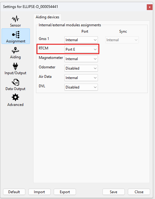
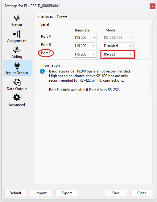
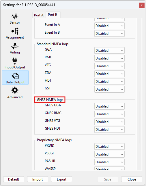
The following example shows the configuration of a serial port (Port E) for RTK correction reception. The steps to follow are:
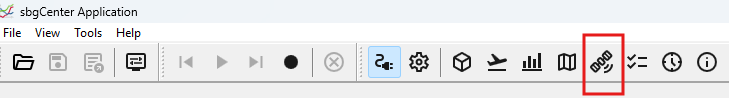
Step 1: Launch sbgCenter and connect to your device. Then click on the configuration icon. In the 'Assignment' tab, choose the serial port for the RTCM correction:
Step 2: In the 'Input/Output' tab, the mode of the selected port for the RTCM correction has to be set to RS-232.
GGA message
Some RTCM providers need to receive NMEA GGA messages from the INS in order to send back the corrections. If this is the case, you can follow step 3.
Step 3 (Optional): If the 'NMEA GGA' message is needed, it has to be set at 1Hz in the 'Data output' tab.
Electrical wiring
The following example is written with an Ellipse-N or Ellipse-D in their serial Hardware configuration. If you have a CAN enabled Hardware variant of the Ellipse, please reach out to us for details.
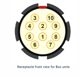
The Ellipse connector
The Ellipse's connector pin out is available on this page Ellipse Boxed: Electrical Specifications
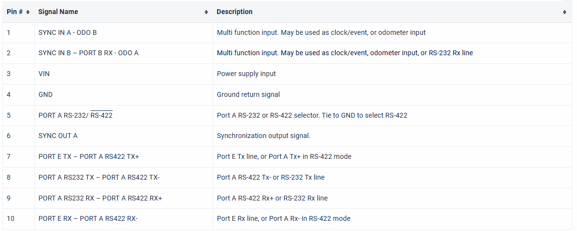
The following pin-out is applicable for all non-CAN versions of the Ellipse:
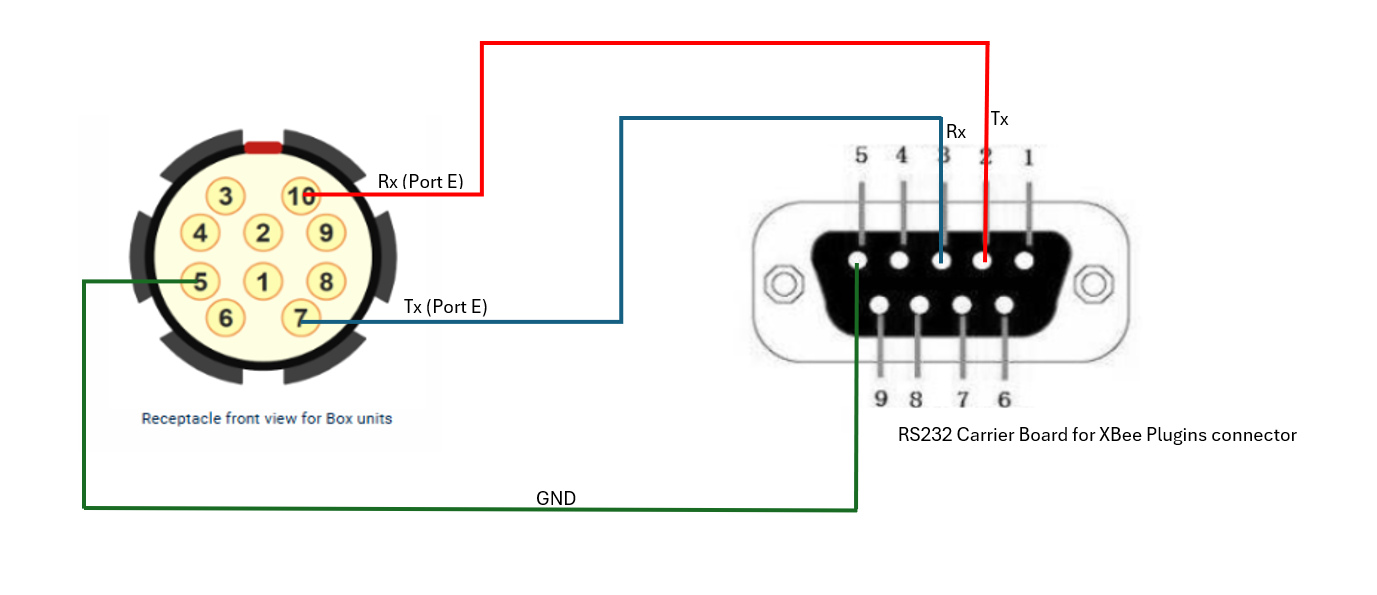
The RS232 Carrier Board for XBee Plugins connector
The RS232 connector is a DB9 female, which has only TXD, RXD, and GND connected. The link setup lines are disabled.
These wiring diagrams show the electrical wiring for the two different options available:
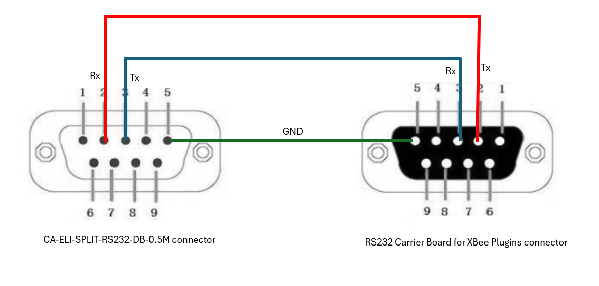
Using the CA-ELI-SPLIT-RS232-DB-0.5M cable:
If the cable CA-ELI-SPLIT-RS232-DB-0.5M is used, the connection could be made directly between the DB9 male (the CA-ELI-SPLIT-RS232-DB-0.5M side) and the DB9 female (the RS232 Carrier Board for XBee Plugins side) or using a straight cable if longer distance is needed. The following electrical wiring diagram shows the connections made:
Making a cable
If you decide to make your own cable, in this case the following pins have to be connected:
Verification
The RTK reception can be checked via sbgCenter by clicking on the GNSS raw information tab as shown in the following picture:
The Solution type in this window will indicates if RTK corrections are being received: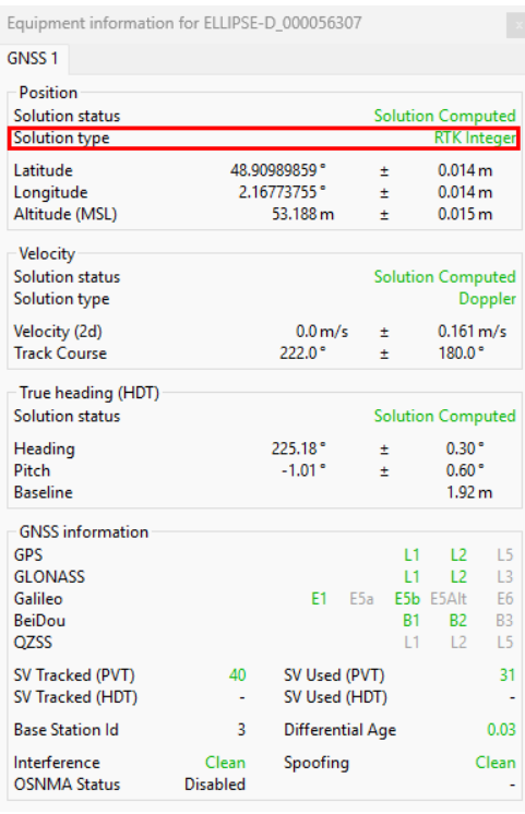
Once everything is set, you can start your mission!