Download PDF
Download page Marine applications.
Marine applications
Doc for Ellipse firmware ≥ 3.0
You are currently viewing the documentation for an Ellipse running firmware version ≥ 3.0. If your Ellipse is operating on firmware version 2.x or earlier, please use the version picker in the top-right corner of the page to select the appropriate version.
This operating handbook explains how to install and setup an Ellipse in marine applications. Mechanical installation is explained as well as software configuration.
Mechanical installation
The INS sensor can be located anywhere in the vessel, considering the following recommendations:
- Sensor is rigidly fixed to the frame
- Sensor is not moving with regard to other equipment (antennas, sonar, LIDAR, etc...)
- Sensor is far from vibrations sources
- Sensor is not exposed to salty water, unless sub-sea casing (IP-68 is not corrosion-proof)
- When relevant (if magnetometers are used), place the sensor away from magnetic disturbances like high current equipment, radios or moving parts.
Note
SBG Systems IMU are designed to handle vibrations without specific care. Nevertheless in case of highly vibrating environment, a mechanical vibration isolation might be required for proper operation. Silicon or wire dampers can be used for that purpose.
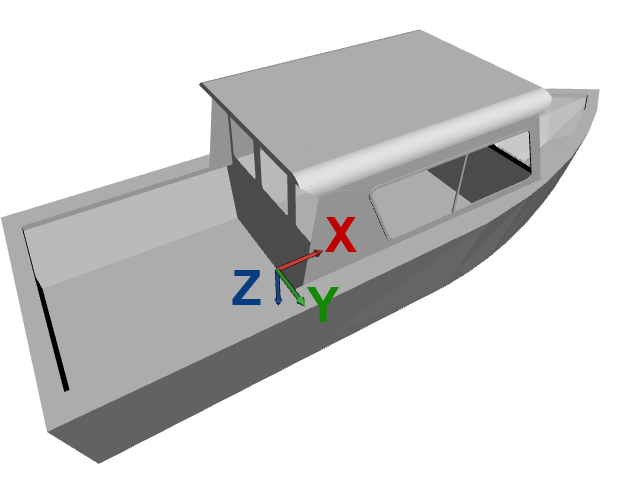
Vessel Reference Frame
The vessel coordinate frame and positive rotations for Euler angles are defined as follows :
- X axis points to the front of the vessel (bow)
- Y axis points to the right (starboard)
- Z axis points the bottom (keel).
Note
The sensor can be placed in any orientation in the vessel. When IMU axes do not match exactly with the vessel coordinate frame, the rough and fine alignment parameters should be corrected through the configuration interface to realign the IMU and vessel coordinate frames.
GNSS setup considerations
When installing your INS with a GNSS aiding, you will need to install the GNSS antennas with a clear view of sky, and fixed with respect to the IMU.
The GNSS lever arms shall also be measured, which are the signed distance, expressed in the vessel coordinate frame, FROM the IMU center of measurements, TO the GNSS antenna.
We usually require these measurements to be precisely performed, within 1cm accuracy.
Note
It's generally not practical to measure with such precision the lever arms, so SBG Systems developed lever arm calibration that enables you to measure rough lever arm estimation (10cm precision) and let the tool refine those measurements.
The GNSS lever arms should be lower than 10m to minimize induced errors.
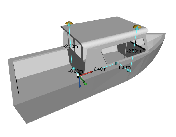
Dual GNSS Antenna Placement
With a dual antenna setup, the INS will be able to keep a stable and precise heading as long as it has a clear GNSS signal. Heading can also be initialized in static conditions.
Dual antenna systems installation will require special care in order to obtain optimal performance :
- The antennas must be fixed with respect to the IMU
- Same antenna type
- Same cables with identical lengths must be used for both antennas. If splitters are used make sure that they are adapted and with the same characteristics
- If antennas are not permanently installed onboard, antennas reference marks (usually the connector position) should be mounted in a repeatable fashion in order to guarantee antennas phase center stability from mount to mount and minimize changes to heading misalignment angle.
- Both antennas must have the same view of sky. Typically avoid placing antennas on each side of a structure or parts that could mask a significant part of the sky
- Baseline of at least 2 meters between both antennas is recommended for best performance
- If the antenna model does not have integrated ground plane, a 10 cm diameter ground plane must be added for both antennas.
Both GNSS antennas lever arms should be measured accordingly.
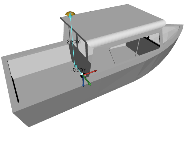
Single antenna installation
Due to the very particular motion of a boat, a system with a single GNSS antenna is recommended only with an INS that supports magnetometers (SBG Ellipse series).
A single antenna installation with GNSS lever arm is shown below:
Software configuration
All Ellipse configuration is done through the sbgCenter interface, or using low level communication protocol. The General configuration handbook details how to configure your INS, and especially the lever arms configuration. Make sure to check it first.
We will see below the specific use cases that are related to the use of your INS for Marine applications.
Sensor motion Profile for marine applications
Different motion profiles are available for marine applications, each designed to meet specific needs. Choosing the right profile is crucial to fully leverage the performance of the Ellipse. To make the best selection, refer to the detailed descriptions provided for each motion profile in sbgCenter.
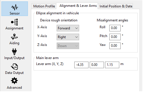
Fine Misalignment configuration for marine applications
Once you have configured the axis misalignment with regard to the vessel, it can be challenging to calculate precisely the residual misalignment to be entered in your configuration, especially the roll and pitch.
These residuals can be measured by using optical, or multi-antenna GNSS systems. For instance, you can leave the vessel in the harbor (where you should expect a zero roll and pitch angles) for a long period and average the unit roll and pitch measured angles. These averaged values should directly be used as misalignment angles.
Aiding configuration
After configuring the alignment and the lever arms of the INS, you should configure the aiding you will use:
- If you want to enable GNSS aiding, the internal GNSS configuration and external GNSS integration page details how to enable and configure a GNSS receiver, both internal or external.
- If you want to enable DVL aiding, the DVL - Doppler Velocity Log integration page discusses the integration of a DVL with the high performance sensors.
- If you want to use the Magnetometer for heading, the Magnetic calibration for marine applications page details how to perform the mandatory calibration process on marine applications.
Operation and heading considerations
With a dual GNSS antenna setup, full navigation data becomes available once GNSS has a correct fix, and the system could initialize the heading angle.
The heading initialization can be performed in static. Ensure the unit is started with a clear view of sky to prevent bad initialization of the GNSS true heading.
The system will maintain accurate heading as long as a good GNSS signal is available.
With a single antenna GNSS Setup, heading needs to be computed using a magnetometers.
Warm-up (Alignment flag)
Once the system is operating in "Full Navigation mode", the warm-up phase can start. In this phase, the sensor fusion algorithm estimates internal sensors biases and scale factors to optimize navigation performance. The system is operational before that time, with consistent quality indicators, but performance may not be optimal in the event of GNSS outages. Depending on conditions, the alignment phase will usually last between 2 to 15 minutes.
Some parameters will directly impact the alignment phase duration :
- RTK or equivalent GNSS solutions may reduce significantly the time needed to estimate the biases.
- Dynamic maneuvers involving accelerations and turns are also ideal to speed up the alignment process.
There is no mandatory pattern to perform, the sensor will only need as much dynamics as possible (orientations and accelerations). Long straight lines should be avoided. A few “eight” figures are sufficient most of the time. A typical alignment pattern is shown in the next picture:

You can check in the status check panel what is the current status of the navigation solution with a few simple indicators.
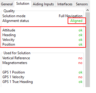
If the alignment status indicates "Aligned" it means the alignment phase is completed and you will be able to benefit of the maximum accuracy of the solution.
Usage without warm-up phase
If, for your use case, you cannot perform a warm-up phase, the INS remains usable but with a lower accuracy during GNSS outage.
The quality statuses (Attitude, Heading, Velocity, and Position) are fully customizable, allowing you to tailor them to your specific application. Use these indicators as a pre-survey check—once they turn green, you're ready to begin.