Download PDF
Download page LiDAR integration.
LiDAR integration
Introduction
In recent years, the use of Light Detection And Ranging LiDAR technology has become increasingly widespread in a number of fields, including surveying. However, despite its mapping capabilities, LiDAR sensors do not inherently provide precise positioning.
By combining a LiDAR sensor with an external position and attitude sensor, it becomes possible to create a very accurate point cloud via a process called georeferencing. Inertial Navigation Systems INS, which rely on accelerometers and gyroscopes to provide continuous and real-time information about the position, orientation, and velocity of a moving platform are the perfect combination to use with a LiDAR for these use cases.
In practical terms, the use of an INS in a combination with a LiDAR can be summed up as follows:
- Data acquisition: the data from the LiDAR and the INS are acquired during a survey mission.
- Point cloud georeferencing: the data from the INS is used to georeference each LiDAR point: the location and the attitude measured by the INS will be used to apply, to each point of a 3D scan, a transformation from the LiDAR body frame to a global reference frame.
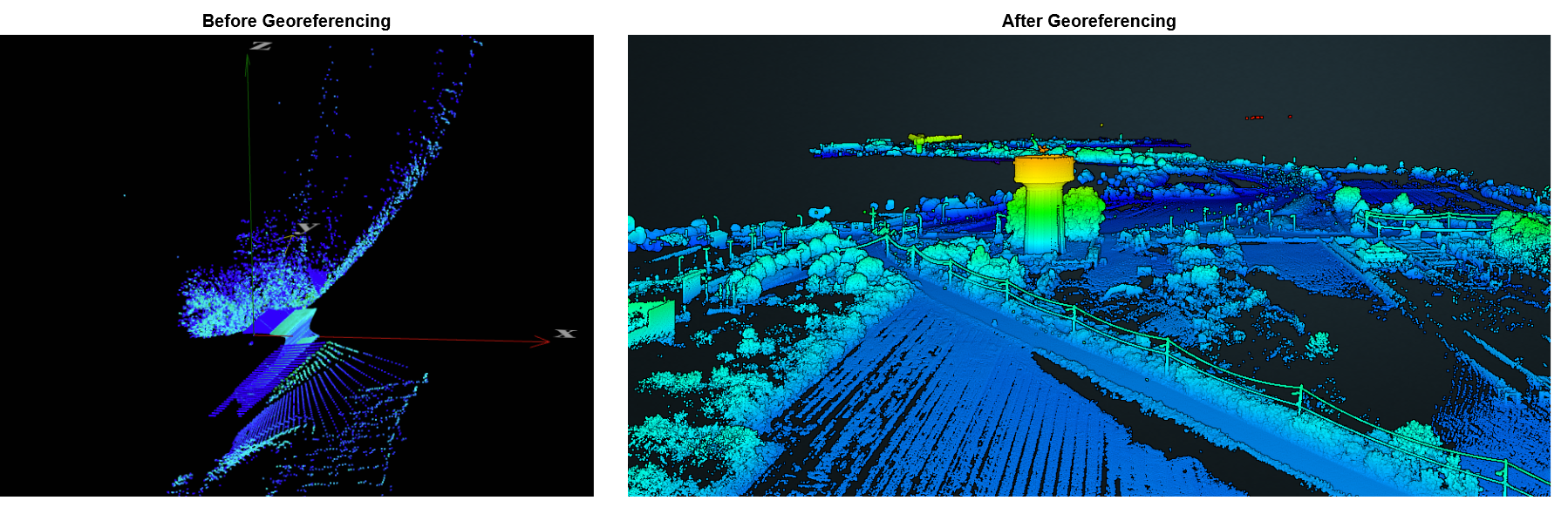
The 2 images below show a cloudpoint generated during an automotive test, before and after georeferencing and correcting orientation. These images highlight the how an INS and LiDAR complement each other.
This operating handbook aims to describe the interface between a LiDAR and a SBG INS from the Ekinox / Apogee / Quanta / Navsight range with the objective of creating a point-cloud using direct-georeferencing methods. This handbook will focus on the 2 key challenges in the integration of an INS with a LiDAR:
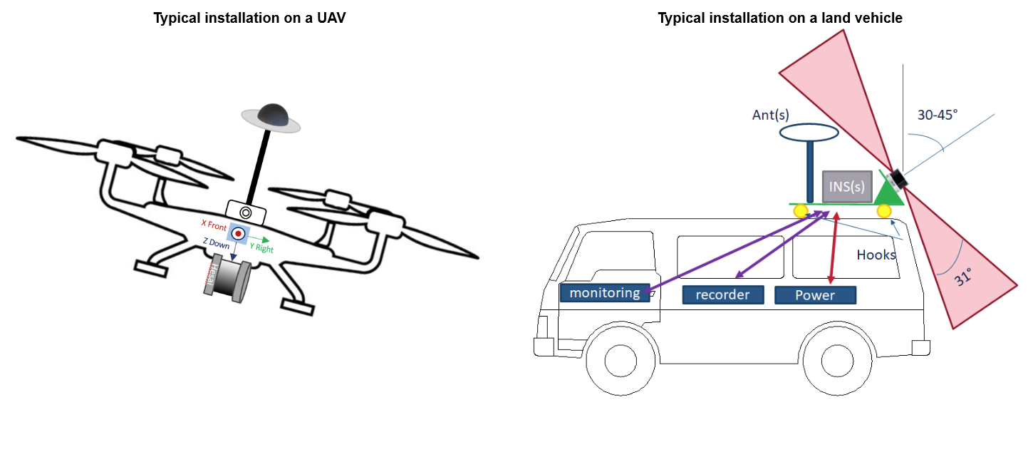
- Mechanical installation: There are multiple possible concerns when conceiving the mechanical parts of an INS + LiDAR system. The guide will detail the most crucial pitfalls and how to avoid them.
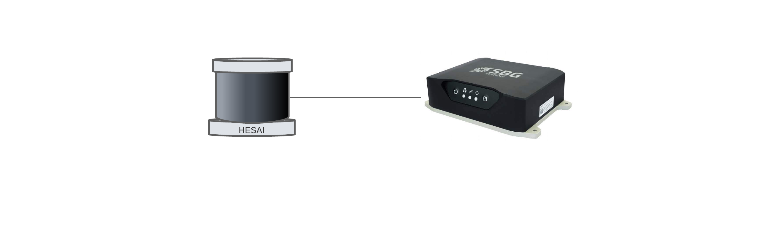
- Synchronization: it is important to ensure that all the clocks of the devices in the systems are aligned to the same time reference. This is mandatory in order to match measurements from the INS and the LiDAR (or other sensors), leading to precise georeferenced data. This guide will use an SBG Navsight-S and a Hesai LiDAR Pandar-XT as an example on how to achieve the synchronization, but the same notions work with a different INS or a different LiDAR.
Mechanical installation
Please consider the following recommendations:
- The INS and the LiDAR should be rigidly fixed on the same support.
- The INS should be static in regard to antenna(s) and LiDAR.
- The LiDAR and the INS should be close to each other to avoid boresight angles instability.
- The INS should be far from strong vibration sources.
- Keep the antenna(s) as far apart as possible from the LiDAR to prevent signal interference generated by many devices on the market.
- The LiDAR placement and orientation should be optimized to maximize the distance covered and the resolution.
Antenna placement
Many LiDAR generate interference and so for many USB3.0 devices, as cameras. So, ensure there is sufficient separation between those devices and GNSS antennas to reduce the risk of electromagnetic interference and signal degradation.
Ideally, the LiDAR, should be in the half-space below the ground-plane of the antenna, which should provide additional protection against most of the direct EM signals.
SBG Systems IMU are designed to handle vibrations without specific care. Nevertheless in case of highly vibrating environment, a mechanical vibration isolation might be required for proper operation and optimal LiDAR data quality. Properly sized silicon or wire dampers can be used for that purpose.
Configuration of SBG INS
The following documentation has been performed using a Navsight-S INS. However all the information applies to all products of the Ekinox / Apogee / Quanta and Navsight range.
What about the Ellipse
The information provided here can also be used for the configuration of an Ellipse to be used in conjunction with a LiDAR sensor. However only the PPS synchronization method would be available ; and the configuration interface and step-by-step guide would differ.
Connect to the unit
The following guide assumes that you are already familiar with the usage of an SBG INS. If you need further details:
- Please refer to the Getting Started section for details on how to connect to the unit.
- To find out more about how to configure your SBG unit for your specific use case, please refer to our Operating Handbooks.
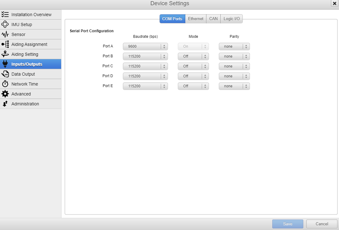
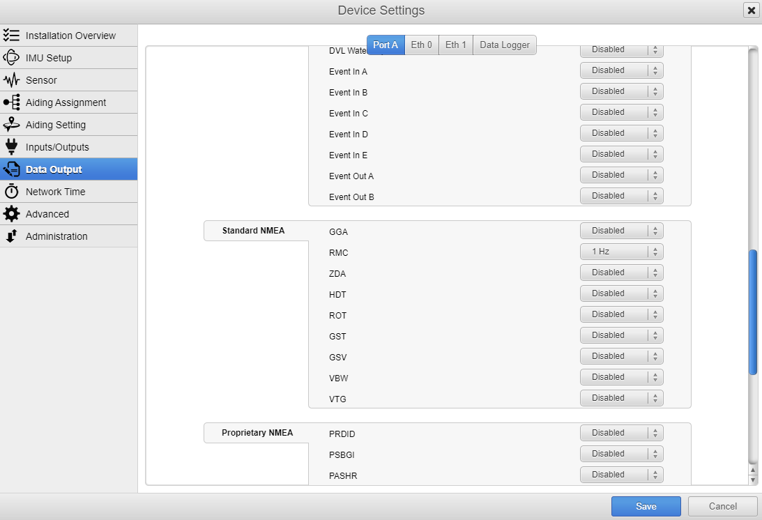
Input / Output configuration
In settings, you'll just need to choose between GGA and RMC NMEA sentences that you want to receive, for this example, we chose to use RMC sentences on port A (it could be another port).
The configuration of the Hesai is straightforward, because one of its input ports is dedicated to GNSS reception. So by default, the communication is serial in RS232 and the baudrate is always at 9600 bps.
Connect to the product
You may need to configure your computer's network settings to communicate with the LiDAR. This typically involves setting a static IP address on your computer in the same network range as the Lidar's default IP address.
Please refer to the LiDAR's manual or user guide to find the default IP address and network settings.
Warning
If possible do not configure the LiDAR to broadcast on UDP if it's on the same network than the INS. Such a setup has the potential to result in network saturation, increased latency, and a heightened risk of packet loss.
If you have to use UDP broadcast, optimizing overall performance and safeguarding data integrity are best achieved when isolating LiDAR and INS onto two distinct networks or adding a hardware firewall, to protect the INS from the overflow of UDP packets.
Synchronization
The synchronization between the LiDAR and the Navsight can be established either:
- by sending a PPS signal from the Navsight to the LiDAR.
- or through a TCP/IP server using Precise Time Protocol PTP.
Both options are adequate for a LiDAR integration ; therefore the choice should be made based on the integration constraints:
- Although PTP is undoubtedly the more modern way, achieving, in the case of a well-tuned network, up to 1 microsecond, it may require more advanced resources and a more detailed configuration.
- On the other hand, sending a PPS signal offers a simpler alternative with very similar performances and may be more suitable in less demanding configurations, it can be considered as the legacy synchronization fashion.
The key is to choose the method that best meets your specific synchronization needs between the LiDAR and INS, taking into account hardware constraints and the requirements of your application.
In the following paragraphs we will detail the recommended topologies, how to configure the INS and the LiDAR in each of the scenarios.
PPS based synchronization
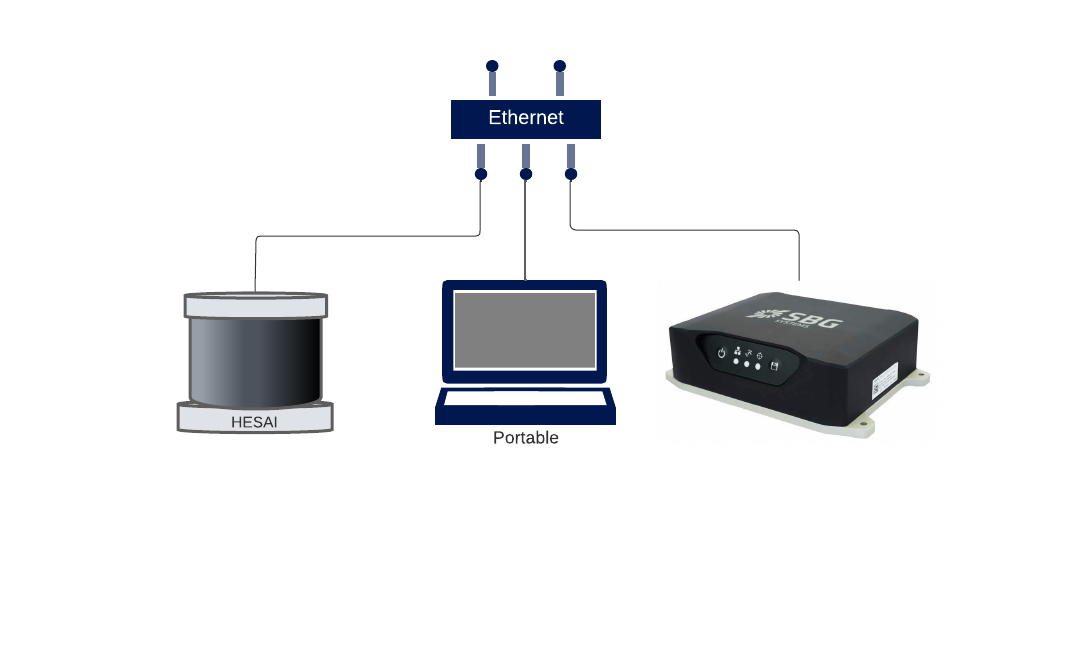
It is recommended to install the INS and LiDAR relatively close to each other to guarantee a short cable (lower attenuation).
| Hesai XT32 LiDAR | Navsight INS |
|---|---|
| Pin #1: PPS (pulse-per-second) signal for synchronization | Pin #1: SYNC OUT-A Synchronization output signal |
| Pin #3 or #5: GND for the external GNSS module | Pin #2: PORT A Signal GND |
| Pin #4: Receiving serial data from the external GPS module | Pin #4: PORT A Tx |
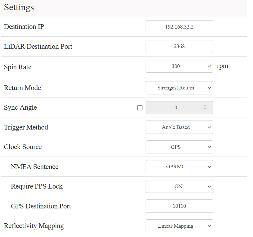
Here you'll configure the INS to send a PPS signal on sync out A for example. And on the LiDAR side, choose GPS for clock source. The Require PPS Lock option should also be activated to prevent your LiDAR from acquiring data when unsynchronized (which in most cases would let you with unusable data)

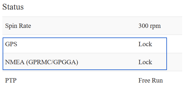
In Home section of the web interface if the LiDAR, you can check if it is receiving PPS signals and NMEA sentences. If it does, you should see the status locked for both NMEA and GPS.
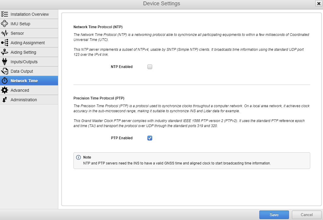
PTP Synchronization
Here in the INS configuration window, you'll configure the IP address of the Navsight to be local, in the same domain as the LiDAR. Then, in Network Time, select PTP.
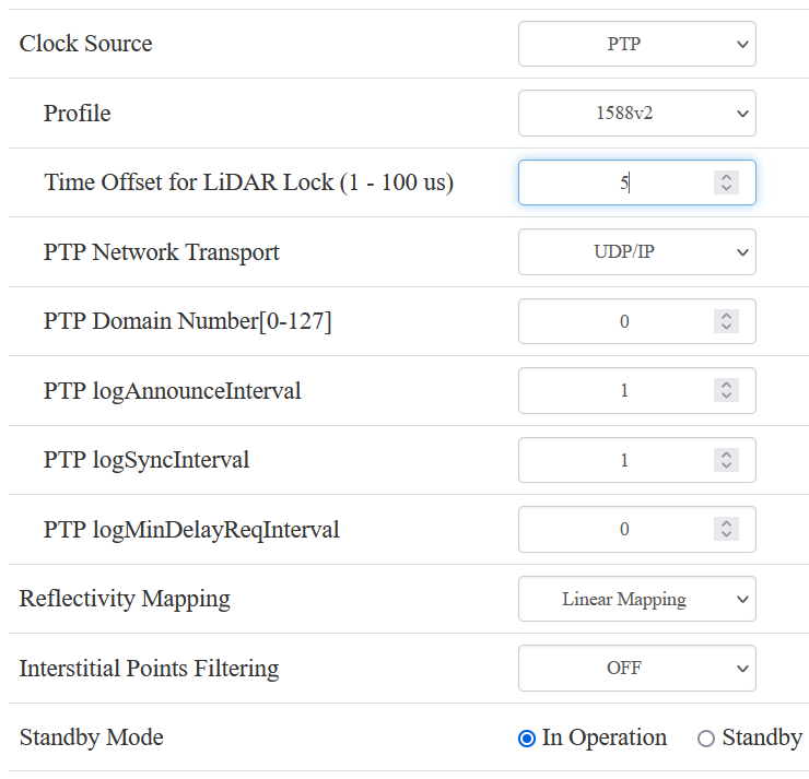
As mentioned in the window, the grand master clock PTP server complies with industry standard IEEE 1588 PTPv2. So from the LiDAR side, please select 1588v2 in profile.
For Time offset for LiDAR Lock you can choose 1 µs if the network is of good quality, which is suitable with a Navsight. But 5 µs also works for most LiDAR applications as long as the vehicle speed is in the usual range.
Then, in PTP network Transport select UDP/IP.
You can leave the default setting for the rest.
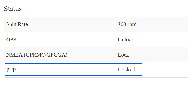
In Home section of the web interface of the LiDAR, you can check if the synchronization works well. If it does, you should see the status Locked for PTP.
Next steps
Once you have acquired synchronized LiDAR and INS data you are ready for the post-processing and the georeferencing.
Maximizing trajectory accuracy
Considering the extreme precision of modern LiDAR sensors, it is always recommended for any survey solutions to perform an Inertial + GNSS post-processing (PPK) to obtain the maximum possible accuracy of the system.
With your SBG INS you can use our own Post-Processing Software Qinertia.
The post processing using Qinertia will yield significant benefits to your survey:
- Improved accuracy in open sky: even in perfect GNSS conditions, post-processing can increase the accuracy of the attitude (roll/pitch/heading) by around 30%
- Maximum accuracy from the first second: every inertial device has a “warm up” phase where it needs to use a reference to estimate its internal errors. By doing multipass processing we can use the full logs to compute the errors and then apply them from the first second of the log. There is no longer the need for time-consuming warm-up periods.
- Reduced impact of GNSS loss: with forward / backward processing we virtually divide the duration of outages by 2.
- Improved reliability: PPK makes survey acquisitions much more reliable by offering multiple ways to process, to recover from an issue, etc. reducing the operational costs of an acquisition.
- Improved quality control: multiple ways to control accurately the accuracy of the measurements, and especially the introduction of separation (difference between the position/attitude computed during the forward and the backward processing) which is a “one stop shop” to assess the quality of the processing, and identify the possible challenging areas
- Improved field workflow: Direct download of correction data by Qinertia streamlines the field setup by eliminating the requirement to deploy a nearby base station. With over 10,000 base stations available worldwide (open access base stations and numerous CORS network), working on broader and more challenging areas becomes more accessible
- Improved Reliability through versatile processing options and geodetic converter: Qinertia offers multiple processing options, including PPK and PPP tight coupling. The geodetic converter seamlessly applies the necessary transformation to pre-configured Coordinate Reference Systems (CRS) based on the selected processing option. This versatility refines the final position estimation, enhancing overall reliability..
Boresighting and Georeferencing
The following steps in the workflow consists in performing the georeferencing (project each point from the LiDAR measurements) and the boresighting (corrections of the misalignment angle between the LiDAR and the INS) using your own tools or third party solutions.