Download PDF
Download page General IMU configuration.
General IMU configuration
This guide aims to show you what are the general web interface options that will be commonly used in all installations.
IMU setup
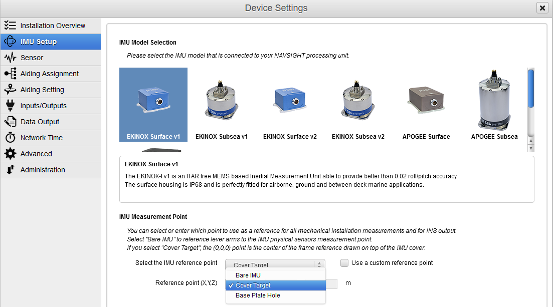
IMU Model selection (Navsight only)
This screen shows the available IMU types. Most integrated systems (e.g. Ekinox-D, Apogee-D, Quanta Micro) won't give the option to change the IMU model.
It's important to select the right IMU model to ensure proper operation.
IMU Measurement Point
All the lever arms measurements (GNSS lever arm, monitoring points, and all other lever arms) are referenced with respect to the IMU.
To ease the lever arm measurement, the interface allows you to setup where should be referenced the measurements on the IMU:
- Bare IMU corresponds to the actual internal sensor center of measurements, as documented in your hardware manual.
- Cover target corresponds to the center of the coordinate frame displayed on your IMU's enclosure, usually on the top.
- Base plate hole corresponds to the small cylindrical alignment hole that is present on your IMU's base plate.
- Custom reference point allows you to enter a specific lever arm, from your actual IMU center of measurement (Bare IMU), to the desired measurement point. This option might be useful for OEM integrators when a visual target is designed outside of the actual IMU enclosure.
OEM IMUs
Note that OEM IMUs only propose the Bare IMU reference point, or the custom one.
Sensor setup
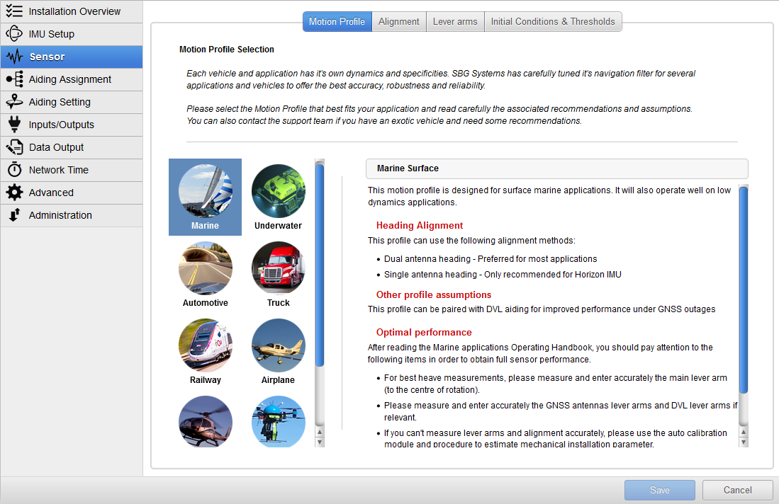
Motion profile selection
This panel allows you to setup the motion profile to fit with your application. Select here the profile that best fits your application to ensure optimal behavior.
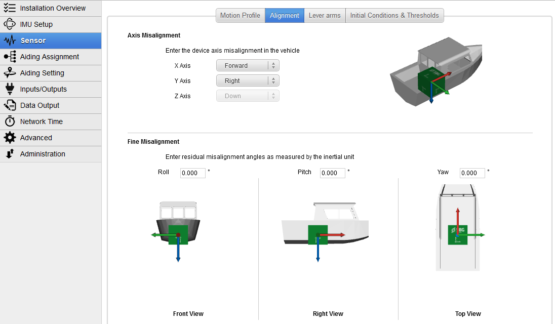
INS Alignment in vehicle
This panel allows you to setup the installation of your INS within the vehicle.
First the axis alignments handles the overall INS orientation in your vehicle, then the fine misalignment allows you to enter fine angles along three axes.
The 3D views are updated in real time to reflect the entered configuration to let you check the consistence of your settings.
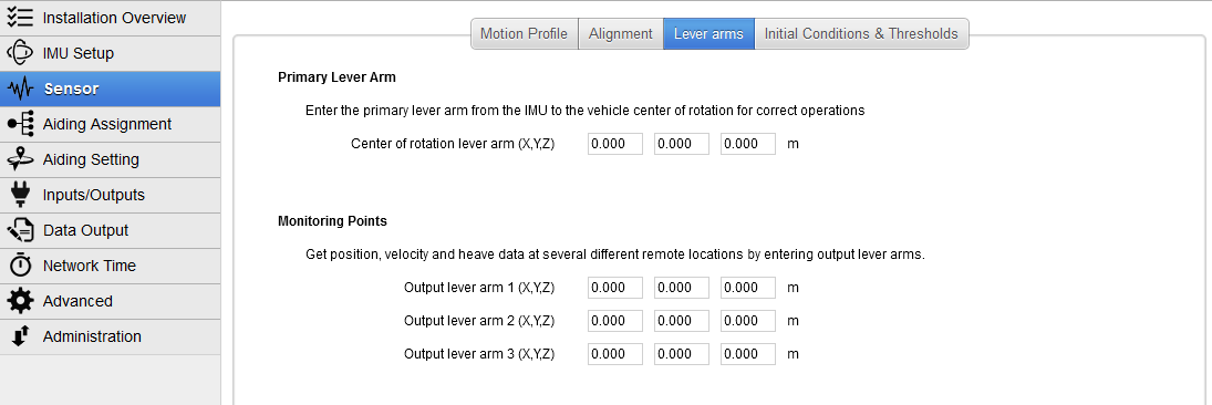
Lever arms
Primary lever arm
This lever arm corresponds usually to your vehicle's center of rotation.
Monitoring points
Your can select here alternative monitoring points to measure the position of dedicated locations on your vehicle.
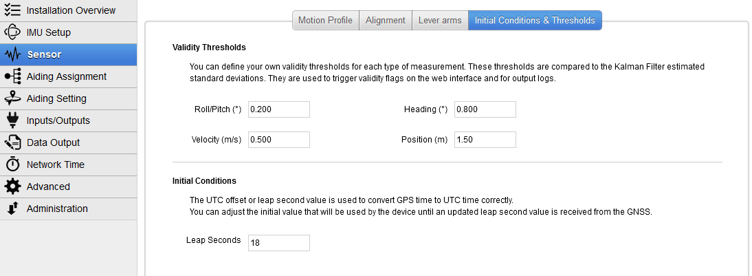
Initial conditions & Thresholds
Validity thresholds
This panel contains advanced information about validity thresholds. Enter here the maximum allowable "valid" information for your application on each of the INS outputs.
Any estimated standard deviation above the thresholds will be marked as "Invalid" in the INS output.
Initial conditions (NMEA receivers only)
Enter here the Leap seconds if some additional leap seconds were inserted after the firmware release to better support NMEA receivers.
Note this setting has no use for internal receivers.