Download PDF
Download page Built-In Tests.
Built-In Tests
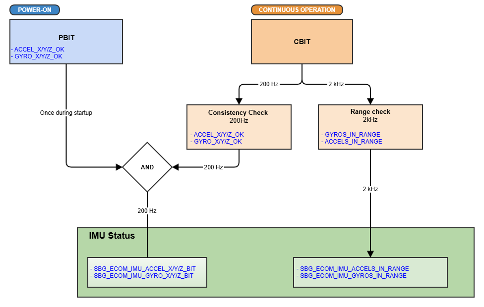
The Pulse-40 OEM continuously monitors the health of its inertial sensors and reports the resulting status through dedicated IMU status flags.
The monitoring architecture consists of three complementary mechanisms:
- Power-On Built-In Test (PBIT), performed once during startup
- Continuous range monitoring, performed at 2 kHz during operation
- Sensor consistency monitoring, performed at 200 Hz during operation
Together, these mechanisms detect sensor faults and determine the status reported for each accelerometer and gyroscope axis.
Built-In Test Overview
1. Power-On Built-In Test (PBIT)
The Power-On Built-In Test (PBIT) is performed once during IMU startup to verify the health of the inertial sensors before normal operation begins.
The following axis-level status flags are initialized from the PBIT results:
ACCEL_X/Y/Z_OKGYRO_X/Y/Z_OK

PBIT Status
If a PBIT status flag is cleared during startup, it remains cleared for the entire power cycle.
2. Continuous Built-In Test (CBIT)
During normal operation, the Continuous Built-In Test (CBIT) continuously monitors the inertial sensors using range and consistency checks.
Measurement Range Checks
Accelerometer and gyroscope measurements are checked at 2 kHz to determine whether they remain within their expected operating ranges.
The corresponding status indicators are:
ACCELS_IN_RANGEGYROS_IN_RANGE
Sensor Consistency Check
A sensor consistency check is performed at 200 Hz. For each sensor type, individual measurements are compared with the mean measurement of the corresponding sensor cluster.
If the deviation of an individual sensor exceeds a dynamic threshold for a sufficient period of time, the corresponding axis status is degraded.
The consistency check can independently clear the following axis-level status flags:
ACCEL_X/Y/Z_OKGYRO_X/Y/Z_OK
Accelerometer Monitoring at High Angular Rates
High angular rates can generate significant centrifugal acceleration, which may introduce apparent inconsistencies between accelerometer measurements even when the sensors are operating correctly.
To prevent false detections, the accelerometer consistency check is temporarily suspended when the angular rate exceeds the applicable threshold.
While the consistency check is suspended:
- accelerometer consistency monitoring is not updated
ACCEL_X/Y/Z_OKretain their last known state
When the angular rate returns below the threshold, the accelerometer consistency filters and accumulators are reset before monitoring resumes.
3. Final IMU Status
The resulting axis-level health status is reported through the sbgECom IMU Status .
For each accelerometer and gyroscope axis, the reported status combines the startup PBIT result with the continuous monitoring result:
SBG_ECOM_IMU_ACCEL_X_BIT = ACCEL_X_PBIT AND ACCEL_X_CBIT
SBG_ECOM_IMU_GYRO_X_BIT = GYRO_X_PBIT AND GYRO_X_CBIT
Status Bit Interpretation
A status bit set to 1 indicates that the corresponding sensor axis is operating correctly. A value of 0 indicates that a fault has been detected.