Download PDF
Download page Data Processing & Filtering.
Data Processing & Filtering
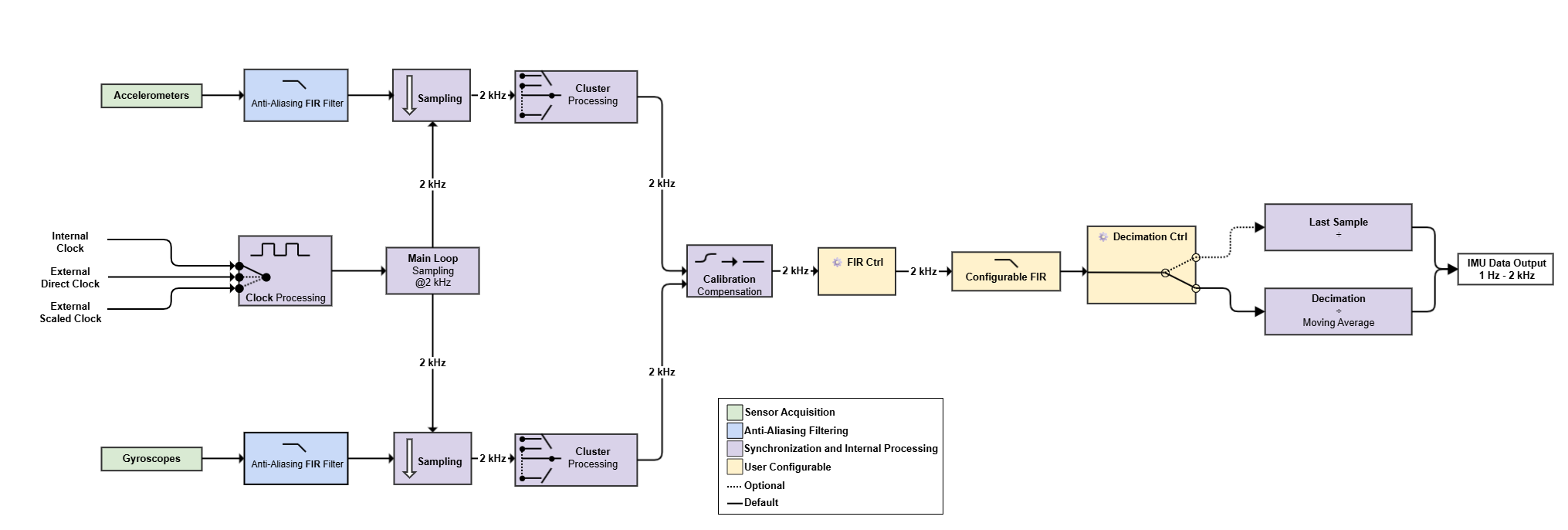
The Pulse-40 OEM acquires acceleration and angular-rate measurements from sensors operating at different native sampling rates. The measurements are filtered, synchronized, calibrated, and converted into a common 2 kHz inertial data stream before user-configurable output processing is applied.
The processing chain consists of two main stages:
- Internal sensor processing: sensor acquisition, anti-aliasing filtering, synchronization, and calibration.
- User-configurable output processing: additional filtering and output-rate decimation.
The first stage generates the internal synchronized 2 kHz IMU data stream. The second stage adapts this stream to the required output characteristics and Output Data Rate (ODR).
Processing Overview
1. Sensor Acquisition
The accelerometers and gyroscopes operate at different native sampling rates. Each sensor stream is acquired independently before being transferred to the common IMU processing loop.
Because the sensor types have different native sampling characteristics, dedicated filtering is applied to each stream before resampling to 2 kHz.
2. Anti-Aliasing Filtering
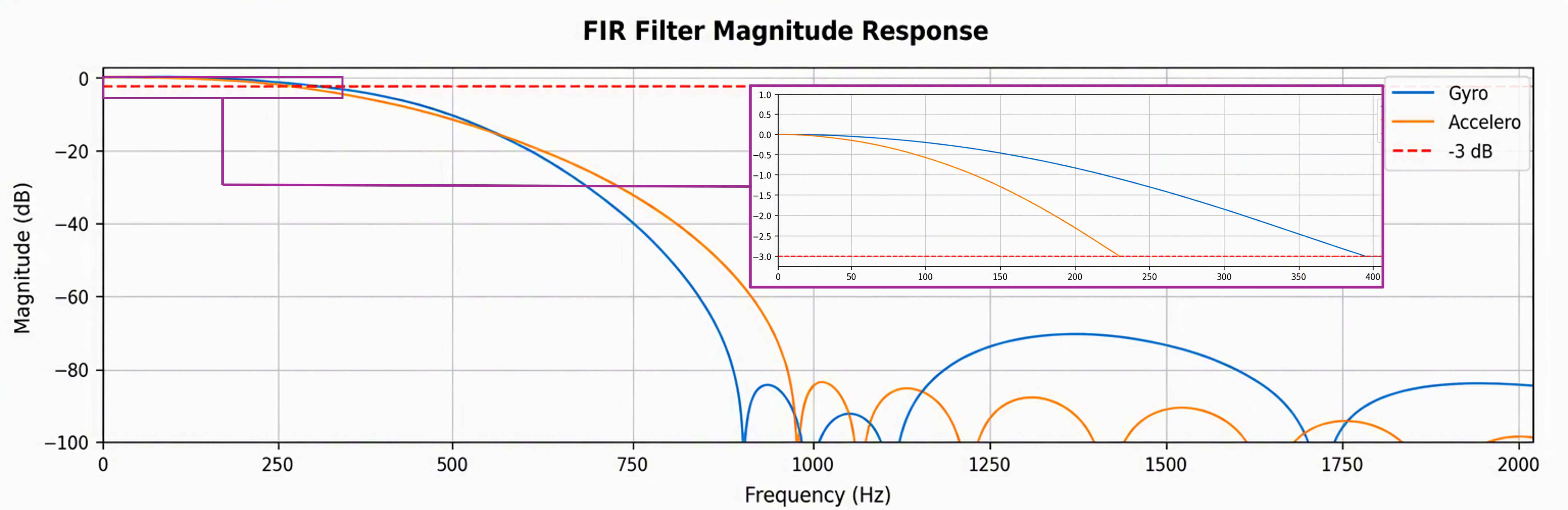
Dedicated FIR (Finite Impulse Response) filters are applied to the accelerometer and gyroscope measurements before they are transferred to the 2 kHz IMU processing loop.
These filters are designed to:
- limit high-frequency content before resampling
- reduce aliasing into the usable measurement bandwidth
- provide a deterministic and approximately constant group delay within the passband
- account for the different native sampling characteristics of the accelerometers and gyroscopes
Signal Characteristics after Anti-Aliasing Filtering
| Characteristic | Accelerometer | Gyroscope |
|---|---|---|
| -3 dB Bandwidth | 250 Hz | 400 Hz |
| Gyroscope to Accelerometer Relative Delay | -0.7 ms | |
3. Synchronization and Internal Processing
After anti-aliasing filtering, the accelerometer and gyroscope measurements are transferred to the common 2 kHz IMU processing loop. This loop can be driven by either the internal clock or an external clock.
The IMU processing loop performs the following operations:
- measurement validity monitoring (CBIT)
- computation of the final cluster measurements
- application of calibration compensation

Clock Control
For optimal measurement accuracy, SBG Systems recommends using the internal clock. When using the external scaled clock, the input period must be a multiple of 500 µs.
4. User-Configurable Output Processing
After calibration, accelerometer and gyroscope measurements are available internally at 2 kHz. Because of their different sensor and filtering paths, the two streams exhibit a small relative delay at this stage.
Output Filtering
An additional FIR filtering stage is applied to the 2 kHz data stream. With the default configuration, this filter reduces the relative delay between the accelerometer and gyroscope measurements while providing a common 250 Hz bandwidth.
This filtering stage is user-configurable , allowing its characteristics to be adapted to the application requirements.
Signal Characteristics with Default Output Filtering
| Characteristic | Accelerometer | Gyroscope |
|---|---|---|
| -3 dB Bandwidth | 250 Hz | 250 Hz |
| Gyroscope-to-Accelerometer Relative Delay | -0.005 ms | |
Output Rate Decimation
After output filtering, the 2 kHz internal data stream is decimated to the configured Output Data Rate (ODR).
By default, all 2 kHz samples available within an output interval are averaged using the movingAverage mode.
When averaging is disabled, the last available 2 kHz sample before the corresponding ODR trigger is used instead.