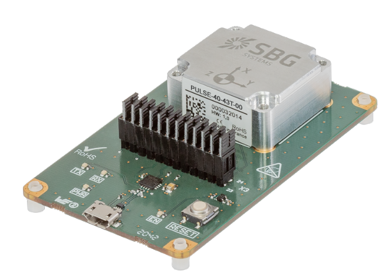
The Development Board is a breakout board for PULSE-40 IMUs products. It provides a simple USB to UART bridge interface, along with a 24-pin, dual-row, 2.54mm connect interface that supports simple connection with remote processor boards, using wire jumpers.
It includes 4x M2.5x0.45mm machine screw holes to support IMU direct-mounting and 4x M3x0.5mm mounting holes in corners.
The Pulse-40 OEM should not be screwed onto the development board, as this may create mechanical stress and damage the connector.
The development board being intended for desk testing, this has no functional impact.
Directly access the Pulse-40 signals
All Pulse-40 signals can be accessed by removing the corresponding jumpers from X3 dual row connector.
The following table shows the table of correspondence between X3 pins and Pulse-40 functions.
X3 pins
Pulse-40 connector pin
Signal
1-2
1
VDD
3-4
2
GND
5-6
3
EN
7-8
4
RESERVED
9-10
5
UART_TX
11-12
6
UART_RX
13-14
7
RESERVED
15-16
8
RESERVED
17-18
9
RESERVED
19-20
10
RESERVED
21-22
11
SYNC
USB interface
The development board features a simple USB Mirco connector to easily connect the system to a computer and power on the IMU.
The USB chipset is a FT230 serial to USB bridge that is supported on all modern operating systems.
The Pulse40 supports baudrates at up to 4 Mbit/s however, the development board is limited to speed of 3 Mbit/s.
RESET
RESET push button manage the EN signal input thanks to a voltage supervisor.
During Power-On : EN signal remains low during 400 ms fixed delay after Power-On : RESET is active, then the EN signal is asserted : RESET is inactive
Normal Operation : EN signal remains asserted
Manual RESET : By pushing the RESET button, the EN signal remains low during 400 ms fixed delay : RESET is active, then the EN signal is asserted : RESET is inactive
LEDs interface
PWR LED (Green) is ON only when power supply is available on USB connector
EN LED (Red) is ON when RESET is inactive, and OFF when RESET is active
TX LED (Red) is ON when USB to UART bridge send data to PULSE IMU ( Transmit data LED drive : PC→ PULSE )
RX LED (Green) is ON when USB to UART bridge receives data from PULSE IMU ( Receive data LED drive : PULSE → PC )
When data is being transmitted or received the respective pins of the transceiver will drive from tri-state to low in order to provide indication on the LEDs of data transfer. A digital one-shot is used so that even a small percentage of data transfer is visible to the end user when he opens the "Basic logger".