The Pulse-40 OEM has been designed to meet the highest requirement in term of electro-magnetic compatibility. As such, the power supply and all digital I/O have been carefully designed. All electrical specification are given in the following table.

ItemMinTypicalMaxUnit

Power supply


Input voltage

3.0

3.3

5.5

V

Power consumption


0.30


W

EN input


Low level threshold


-

0.3

V

High level threshold

1.2

-

-

V

Input current

120

-

600

µA

LVTTL inputs


Low level input voltage

-

-

0.8

V

High level input voltage

2

-

-

V

Input current

- 20

-

- 40

µA

LVTTL outputs


Low level output voltage

-

0.0

0.4

V

High level output voltage

2.8

3.3

-

V

Max output current

0

-

20

mA

Power supply level

The Pulse-40 OEM v2 supports a power supply range from 3.3 V to 5.0 V. The recommended operating voltage is 3.3 V, as it provides optimal thermal performance.

Operation at 5.0 V is possible but results in higher heat dissipation. It is provided for backward compatibility with the Pulse-40 OEM v1 and has not been fully qualified. It is therefore not recommended for new designs.

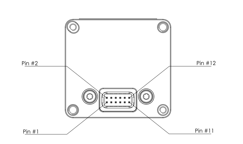
Connector Pin Assignment

The table below give manufacturer and model number of the recommended mating connector.

Connectors

Manufacturer

Manufacturer P/N

Description

Comment

Pulse-40 connector

ANTELEC

AM2D-127-12-4.7-3.8-G-CMS-H25-P

Connector, Male, Vertical, 6+6 , 1.27mm pitch, Locating Pins, SMD


Mating Connector

HARWIN

M50-3120645Connector, Female, Vertical, 6+6 , 1.27mm pitch, 3.8mm height (max), SMDOctopart: M50-3120645

Note that most of Dual In-Line, 1.27mm pitch, 3.8mm height square connectors could be used.

Main connector pin-out

The following table describes the connector pins function.

Pin#NameType (input/output)DescriptionConnection Tips

1

VDD

Power Input

Power Supply Input

--

2

GND

Ground return

Power Supply Ground return & Signal reference

--

3

EN

Input

Power enable

Tie to VDD for nominal operation

4

RESERVED

-

Reserved for future use

Leave unconnected

5

UART_TX

LVTTL output

UART Data Transmit Signal

Leave unconnected  if not used

6

UART_RX

LVTTL input

UART Data Receive Signal

Tie to 10k Ohm pull-up resistor if not used

7

RESERVED

-

Reserved pin for future use

Tie to GND with a 10k Ohm Pull Down Resistor or leave unconnected.

8

RESERVED

-

Reserved pin for future use

Leave unconnected

9

RESERVED

-

Reserved pin for future use

Leave unconnected

10

RESERVED

-

Reserved pin for future use

Leave unconnected

11

SYNC

LVTTL Input/Output

General purpose input / output. May be configured in one of the following modes:

  • High impedance*
  • SYNC OUT
  • SYNC IN

Leave unconnected if not used

12

TX_EN

LVTTL Output

TX_EN, Driver enable signal for RS485 transceivers

Leave unconnected if not used

*Pin 11 is set in high impedance mode by default