Mounting the Pulse-40
The Pulse-40 contains a smart set of holes that are partially threaded. This allows you to mount the IMU from the PCB bottom using 4x M2.5 screws, or from the top, using 4x M2 screws and external nuts.
Specifications
All dimensions are expressed in millimeters using the International System of Units (SI) conventions.
| Parameter | Specification |
|---|
| Size | 30 x 28 x 13.3 mm |
| Weight | 12 g |
| Material | Aluminum |
| Surface Treatment | SURTEC 650 |
| Top Mounting | 4x Diam. 2.2 mm, clear holes for M2 x 16 mm screws Torque: 0.2N.m (higher torque will negatively impact performance) Use of thread locker is strongly recommended due to the low torque. |
| Bottom Mounting | 4x M2.5 x 6 mm, threaded holes for M2.5 x ( 7.5 + base thickness ) mm screws PCB ( 1.5 mm th.) mount example: 10 mm long screws Torque: 0.25N.m (higher torque will negatively impact performance) - Use of thread locker is strongly recommended due to the low torque. |
| IP rating | IP-50 |
| Connector | Contact Base Material : Copper Alloy Finish : Gold Flash Insulation : nylon-6T, UL94V-0 |
The enclosure is not waterproof, the Pulse-40. Proper system sealing if the Pulse-40 has to be used in a humid environment.
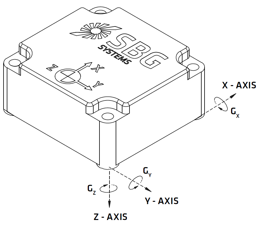
Directions of sensors axes
Device coordinate frame is marked on the IMU cover using laser engraving. The inertial frame is defined as a standard right-handed North, East, Down (NED) frame (X,Y,Z) as represented in the picture. According to the “Right Hand Rule”, the rotations are positive clockwise in the axis direction as represented in the drawing below.
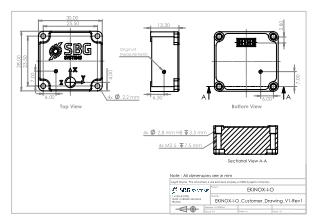
Origin of measurements
Because the Pulse integrates several MEMS accelerometers, it integrates a built-in size effect compensation and as a result a ‘virtual’ reference point has been chosen to define the Origin of Measurements Point. The origin of measurements, is the point where the inertial frame, as defined by the accelerometers triad, intersect.
The Origin of Measurement Point is represented by the red target on the drawings under.
Mechanical Drawing
In the following drawings dimensions are in millimeters.
3D Files
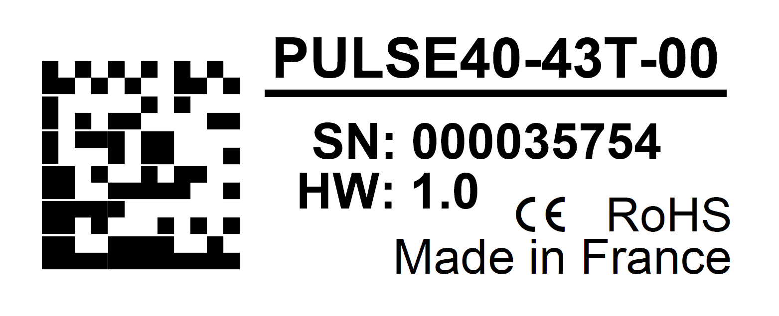
Label
SBG Systems manufacturing process is based on EN-9001 system with individual and full traceability of every component and operation. Each unit is identified by a unique serial number that can be used to trace all operations during the product lifetime such as manufacturing, calibration, tests and repairs.
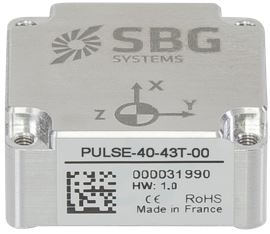
In addition to a unique serial number, a product code is used to define exactly the device type, options, configuration. You can find on the side of the Pulse cover a laser printed label that hold all these identification information. This label also includes a data-matrix code that encodes the device unique serial number.