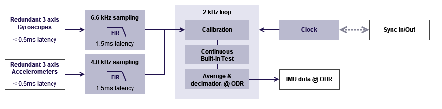
Overall signal processing architecture
The accelerometers and gyroscopes are first sampled at high rate (6.6kHz for gyroscope and 4.0 kHz for accelerometer) to maximize sampling resolution and gain immunity in vibrating conditions. A FIR low pass filter ensures proper anti-aliasing and allows the signals decimation to a lower frequency.
A 2 kHz loop that can be controlled either by the internal or an external clock performs the all the calibration tasks and sensor average and down sampling task using a moving average filter, providing an aliasing free output at the desired Output Data Rate (ODR).
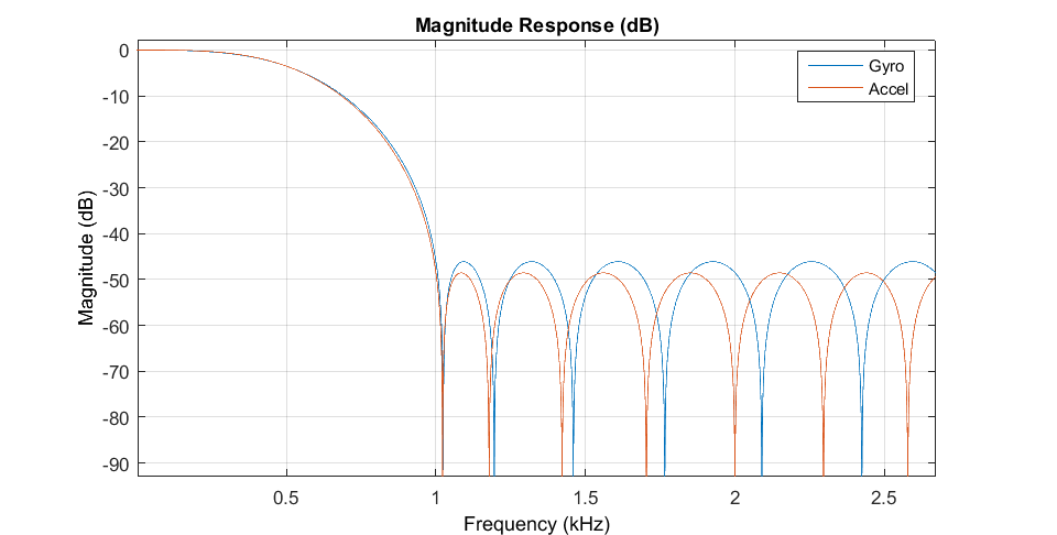
Accelerometers and gyroscopes frequency response
The following bode diagram shows the frequency response of accelerometer and gyroscopes after the first FIR filter.
Both filters have a constant phase response and a delay of 1.5ms.
Output Data Rate (ODR) handling
The internal computation loop runs at 2KHz, but user can freely define a different output data rate (ODR). In the case the ODR is lower than 2KHz, the samples will be summed and averaged to ensure there is no aliasing at user output.
Moreover, the moving average filter acts exactly like a high frequency integrator, so this scheme is ideal for inertial sensor coupling with an INS filter.
Continuous Built-In Test
A really useful feature of Pulse-40 is it's ability to monitor in real time the robustness of its measurements.
Thanks to its redundant architecture, the sensor measurements are continuously monitored. In case an internal sensor measurement is not consistent with the others, a CBIT flag warns the user about this performance issue.
This indicator should be used in critical applications as IMU validity indicator.