Download PDF
Download page Serial interface board.
Serial interface board
Introduction
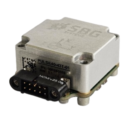
The Serial interface Board is a conversion interface for Pulse-40 IMUs converting the signals from UART over LvTTL to RS422.
It provides a simple and compact solution to connect and test the Pulse-40 with a system using RS422 for long range connectivity.
It offers the same mechanical interface as the Pulse-40: 4x Diam. 2.2 mm, clear holes for M2 screw
Interface specifications
Connector
Connectors | Manufacturer | Manufacturer P/N | Description |
|---|---|---|---|
Product Connector | NICOMATIC | 221V10F26 | Connector, Male, 10cts, 2mm pitch, PCB mounted, 90° TH |
Mating Connector | NICOMATIC | 222S10M16C | Connector, Female, 10cts, 2mm pitch, Jackscrews, Straight, 24-28 AWG conductors |
| NICOMATIC | 222C10M16C | Connector, Female, 10cts, 2mm pitch, Jackscrews, Straight, 22 AWG conductors | |
| HARWIN | M80-4811005 | Connector, Female, 10cts, 2mm pitch, Jackscrews, Straight, 24-28 AWG conductors | |
| HARWIN | M80-4801005 | Connector, Female, 10cts, 2mm pitch, Jackscrews, Straight, 22 AWG conductors |
Pin-out
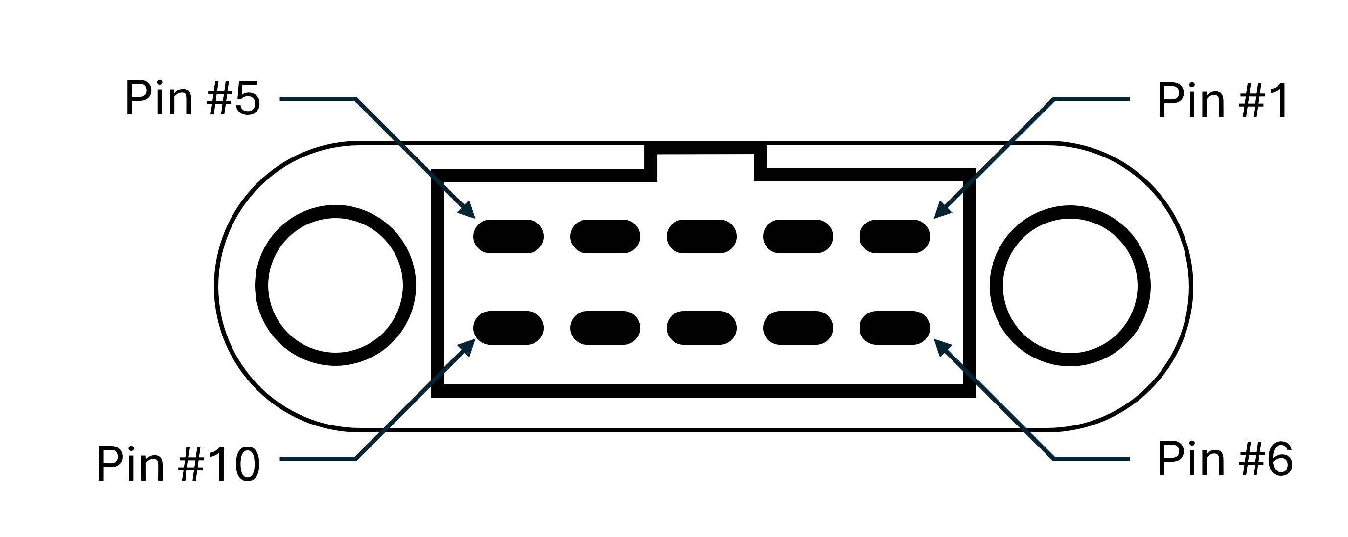
| # | Signal | Type | Description |
|---|---|---|---|
1 | VIN | Power Input | Power Supply Input |
2 | RS422_TX_N RS485_B | RS-422 Output RS-485 Input/Output | RS-422 Mode : Data Transmit Output Signal (- differential) RS-485 Mode : Data Transmit/Receive Input/Output Signal (- differential ) |
3 | RS422_RX_N | RS-422/RS-485 Input | Data Receive Signal (- differential), features 120Ohm termination resistor |
4 | RS422_SYNC_N | RS-422 Input/Output | Synchronization Input or Output Signal (- differential), software defined |
5 | RS422 / RS485 | RS-422 Input | RS422 / RS485 interface mode selection pin
|
6 | GND | Power and Signal Ground | Power Supply Return and Signal Reference |
7 | RS422_TX_P RS485_A | RS-422 Output RS-485 Input/Output | RS-422 Mode : Data Transmit Output Signal (+ differential) RS-485 Mode : Data Transmit/Receive Input/Output Signal (+ differential ) |
8 | RS422_RX_P | RS-422 Input | Data Receive Signal (+ differential), features 120Ohm termination resistor |
9 | RS422_SYNC_P | RS-422 Input/Output | Synchronization Input or Output Signal (+ differential), software defined |
10 | GND | Signal Ground | Ground Reference for signals |
Mating cable
SBG Systems sells open-ended mating cables: 26AWG, 50cm long open-end cable.
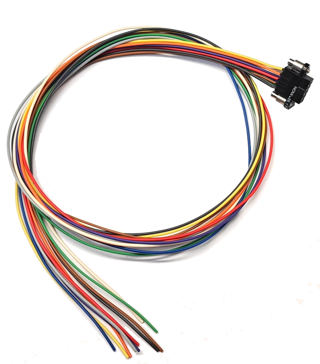
Pin-out
| # | Wire Color |
|---|---|
1 | Black |
2 | Brown |
3 | Red |
4 | Orange |
| 5 | Yellow |
6 | Green |
7 | Blue |
8 | Violet |
9 | Grey |
10 | White |
Electrical specifications
Description
Power Supply, I/O and Serial Interfaces electrical specifications. The following tables document the nominal recommended operation conditions.
Refer to Interface Specifications for more details about onboard and mating connectors.
Power Supply
| Item | Conditions | Min. | Typ. | Max | Unit |
|---|---|---|---|---|---|
Input Voltage Range | - | 4.75 | 12 | 36 | V |
Power Consumption | Over Full Input Voltage Range | - | 0.40 - 0.70 | - | W |
Inrush Current Consumption | - | - | - | 750 | mA |
| Under-Voltage Lockout Threshold | Rising | - | 4.6 | - | V |
| Falling | - | 4.3 | - | V |
RS-422 & SYNC Interfaces
| Item | Conditions | Min. | Typ. | Max | Unit |
|---|---|---|---|---|---|
Receivers | |||||
Input Differential Threshold | -7V<VCM<+12V | -200 | - | -45 | mV |
Input Hysteresis | - | 30 | 50 | mV | |
Input Resistance | - | 102 | 120 | 138 | Ω |
Transmitters | |||||
Differential Output Voltage | RL=100Ω | 2 | 4 | V | |
Common Mode Output Voltage | RL=100Ω | 3 | V | ||
I/O Interfaces
| Item | Conditions | Min. | Typ. | Max | Unit |
|---|---|---|---|---|---|
RS422/!RS485 interface mode selection pin | |||||
Input Range | - | 0 | 5.5 | V | |
Low Level Threshold | - | 0.8 | V | ||
High Level Threshold | - | 2 | V | ||
Pull-up Resistance | - | 4.7 | kΩ | ||
Electrical Absolute Maximum Rating
Stresses above those listed under the Absolute Maximum Ratings may cause permanent damage to the device.
This is a stress rating only; functional operation of the device at these or any other conditions above those indicated in the operational section of this specification is not implied.
Exposure to absolute maximum rating conditions for extended periods may affect device reliability.
RS-422 & SYNC to Ground | ±16 | V |
| RS422/!RS485 to Ground | –0.5 to +6.5 | V |
| VIN to Ground | ±40 | V |
ESD Circuit protection for all pins | 30 | kV |
Note: The product chassis is internally connected to Ground.
Mechanical
Specifications
| Parameter | Serial Interface board |
|---|---|
| Size |
|
| Weight | TBC |
| Mounting | Mounting from top 4x M2 (recommended DIN912 M2 L20 INOX A4 depending on mechanical interface) Torque: 0.2N.m (higher torque will negatively impact performance) Use of thread locker is strongly recommended due to the low torque. |
| IP rating | no ingress protection |
| Other environmental specifications | The interfaced board has not been specifically tested in environments (temperature, vibrations, etc). |
Drawings
3D view
A step file of the board is available for mechanical overview: Step - Pulse-40-RS422 Interface Board.step