Download PDF
Download page Accounting for misalignment.
Accounting for misalignment
The sensor alignment procedure involves two steps: an axis alignment, and a fine alignment. Some aiding sensors must also take into account misalignment, that will be measured like it has been done for the IMU, comparing the external sensor with vehicle coordinate frame.
Axis misalignment
The following example shows how to measure IMU axis misalignment. The IMU axes must be compared to the Vehicle axes as follows:
| IMU AXIS | Vehicle direction |
|---|---|
| X | LEFT |
| Y | FRONT |
| Z | DOWN |
Axis Example alignment


Fine misalignment
Once axes axis misalignment is performed, the small residual angles must then be measured as follow. Misalignment angles correspond to the residual rotation required to pass from the IMU coordinate frame to the vehicle coordinate frame. In our example, alpha corresponds to the mis-heading and its sign is negative.
Most applications will only have low angles on roll and pitch misalignment. If large angles on roll and pitch are expected (> 5°), user must consider the rotation composition order: roll, then pitch, then yaw.
| Mis Angles | Value |
|---|---|
| misroll | Not Shown |
| mispitch | Not shown |
| misheading | -α negative) |
Misalignment residuals Measurments:


Once the fine misalignment angles are measured and entered into the device configuration, the sensor coordinate frame is assumed to be aligned with the vehicle coordinate frame.
Vehicle roll, pitch and yaw misalignment
When the sensor is installed on a vehicle that lies on the ground (not applicable to boat), it is easy to estimate the roll and pitch misalignment using a simple procedure.
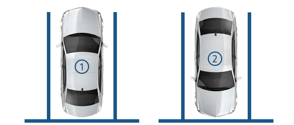
The procedure is applicable on any flat surface (not necessarily horizontal). If we consider a car, it consists in:
- Parking the car in reverse direction on a parking slot, then once stopped, measure the roll and pitch angles.
- Parking the car in forward direction on the same slot. Measure the roll and pitch angles.
- Use the mean roll and mean pitch as respective roll misalignment and pitch misalignment settings in the configuration page.
Measuring the INS heading misalignment is however much more complicated. Several methods can be used to do so as soon as you can guarantee your vehicle is a standard car with non steering rear wheels:
- You should first enter the measured roll and pitch misalignment in the INS configuration.
- Then drive your car in straight lines with sections above 50 km/h and make sure you don’t drift.
- Use the mean slip angle value as a direct measurement of the heading misalignment.
- You can also use Qinertia to automatically estimate and display yaw, pitch and vehicle Center of Rotations lever arms
IMU misalignment interaction with other aiding sensors setup
Important notice
It's worth noting that the IMU misalignment angles are assumed to be entered before any other aiding sensor configuration. In particular, the aiding sensors that require specific calibration or lever arm setup will be affected by any change in the IMU misalignment setup. This remarks is particularly true for:
- Magnetometers aiding and magnetic calibration
- GNSS lever arms and dual antenna GNSS setup
- DVL alignment
If a particular user installation requires to reconfigure the IMU misalignment angles, please run all lever arm setup, aiding alignments and magnetic calibration steps again.