Download PDF
Download page Time, synchronization and event management.
Time, synchronization and event management
This documentation is not applicable for the PULSE-40 product. For more details on the PULSE-40 clock modes and its timing and synchronization, please check our specific documentation.
When working in a system with different devices that continuously communicate/log time-stamped data, the synchronization of the devices' clocks is crucial to be able to consolidate the data.
This article addresses the clock management within the SBG system. To begin, we will provide an in-depth understanding of the different calculation delays within an SBG INS. Following that, we will see how an SBG INS synchronizes its own clock with UTC time. Finally, we will explore the different tools to synchronize SBG products with other devices.
INS output latency
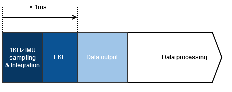
The output latency is an important aspect in real time control applications, where a higher output latency could degrade control loops performance. SBG INS embedded software has been designed to minimize output latency: once sensor data are sampled, the Extended Kalman Filter (EKF) performs small and constant-time computations before the outputs are generated.
Typically the observed output delay is less than one millisecond.
Note that CAN Logs might be received after all serial outputs because the CAN protocol cannot guarantee the output delay in case of traffic on the CAN bus.
Good to know
The processing latency should be added to the data transmission latency if you want to get total delay. This transmission latency vary from one interface to another.
For instance, a 50 bytes message sent on a UART interface at 115200 bps will take 4ms for complete transmission. Consider higher baudrates to minimize output latency.
Events
Event inputs
Inertial sensors can include up to 5 synchronization inputs that can be used for different purposes:
- Event triggered logs: All pulses received generate events that can generate specific Logs output. Any output log can be triggered by an event pulse.
- Event Marker: An event marker log can be sent each time a pulse is received in order to time mark each event.
- PPS input: When connected to an external GNSS system, the PPS signal is used to realign and synchronize internal clock to GPS clock.
- Other aiding input timestamping: If a specific aiding sensor generates pulses that time stamp the following output, the corresponding event input can be used for data synchronization.
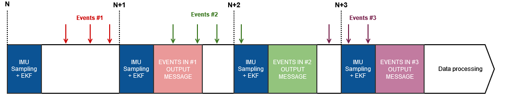
Event triggered logs
In this mode of operation, the inertial device runs on its own clock to sample sensor data and compute the inputs.
Once a new output is ready to send, the system will simply check if an event input was received during last processing loop, and will send the output messages accordingly.
This mode of operation may induce an output jitter of up to 5ms due to the synchronized internal and host clocks.
Warning
SBG Systems sensors handle up to 200Hz input for output log triggering. In case of higher frequency events, only the last received event will be considered for message triggers.
Event markers handling
Event markers allows you to precisely measure the time of events such as camera shutter time, up to the microsecond precision. Once received, events inputs are precisely timestamped and stacked in the system and a marker output message will be sent during the next message output window.
This log will include all events received during previous loop.
Warning
SBG Systems sensors handle up to 1kHz event Marker’s input. Sending more than 1KHz events may overload the internal CPU.
Event output
The INS can be used to synchronize other devices by generating pulses on a synchronization output pin.
These pulses can be generated based on the following modes:
- Main loop divider: an event is sent at the beginning of an INS loop (at the sensor sample time). A divider can be configured to reduce its frequency. For example, If the divider is set to 4, the pulse output frequency will be 200Hz / 4 = 50Hz.
- PPS: an event is sent at the beginning of an INS loop (at the sensor sample time), at 1Hz frequency. If the system is time synchronized with a UTC input, this output is provided at each top of a second in UTC time.
- Virtual odometer: an event is generated each time a configurable distance has been traveled (feature available on our High Performance products such as Ekinox, Apogee, Quanta and Navsight).
Synchronizing with external devices
There are three main solutions to synchronize with external equipment.
- PPS + time messages output. This mode is very similar to common GNSS receivers operation and enables less than 1µs accuracy. See the Event output section of this document.
- Network Time Protocol (NTP) allows for synchronization with a 1 millisecond accuracy on local network.
- Precision Time Protocol (PTP) allows for synchronization with an accuracy of 150 nanosecond to 1µs . It however requires specific Hardware so is not always usable.
Network Time Protocol (NTP)
NTP is a distributed service that synchronizes the clocks of equipment to a coordinated universal time UTC based on TCP/IP networks.
The protocol uses a hierarchical (master-slave topology) of time source, with each level called a Stratum. The highest level (Stratum 0) are the atomic clocks, such as the ones in GNSS satellites. Additional stratums can be added to synchronize equipment on a specific network.
The NTP is only implemented in Stratum 1 to distribute time to other devices. Time is marked as not synchronized until an internal UTC time is available.
NTP uses the UDP protocol, on port number 123.
If you need further details on the NTP protocol you can check the NTP wikipedia page.
Precision Time Protocol (PTP)
Like NTP, PTP is a protocol used to synchronize clocks throughout a TCP/IP network. However it is built to offer a substantially better precision than NTP.
To reach this level of precision, the protocol has a Hardware dependency, and is therefore not applicable on all devices. All SBG inertial devices featuring an Ethernet connection enable the PTP time server, with a measured average time accuracy of 150ns.
The PTP implementation generates a clock marked as faulty in case UTC time is not available internally.
Once UTC time is available, our PTP system can operate as Grand master clock (or passive mode if a higher precision time reference is available on the network).
PTP operates uses the UDP network protocol, on port number 319 and 320.
SBG PTP implementation provides timestamps in TAI time scale.
If you need further details on the PTP protocol you can check the PTP wikipedia page.