Download PDF
Download page How to compare IMU.
How to compare IMU
Sensors on the market will have datashteet that will include all or part of the following specifications. It matters to know the meaning of each of these specifications if present on a datasheet as it is a decision maker to select an IMU.
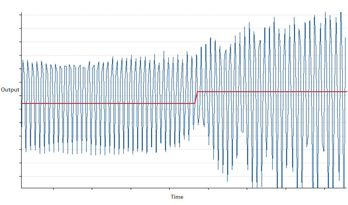
Full Scale
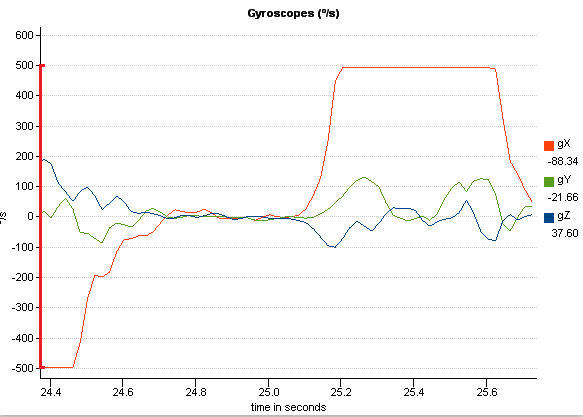
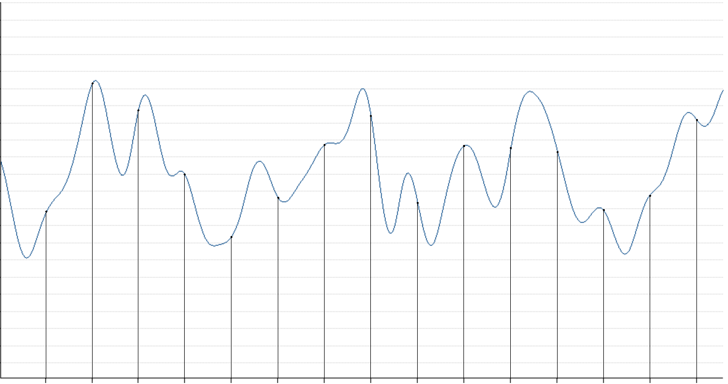
It represents the measurement range were the sensor has been calibrated (for instance +/- 2g on accelerometer or +/-500°/s on a gyroscope), it can usually go a bit further than the maximum specified values, but the accuracy of the measurement is not guaranteed. For instance the next graph shows the gyroscopes saturates at 500°/s, which means any faster rotation will not be measured by the sensor.
It is not recommended to select a measurement range smaller that the expected motion.
Scale Factor Stability
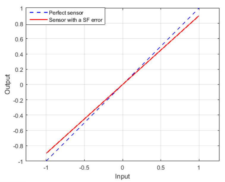
Scale factor error are measurement inaccuracies proportional to the applied motion. An advanced sensor thermal calibration can minimize this kind of errors. SBG Systems specification of scale factor error includes thermal and long term stability errors.
The next graph shows an ideal sensor (in blue) would report the actual input of the motion, while a realistic sensor (in red) would report a slight offset on the output, compared to the actual motion on the input.
Non-linearity
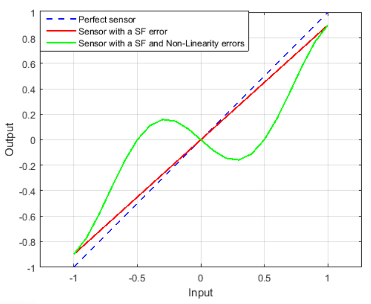
The non-linearity is similar to the scale factor: the output of the sensor is not corresponding to the actual input it should measure. However instead of having an output with proportional error depending on the full scale (in red) it will actually varies in a more complex way (in green).
Non linearity errors can be minimized by advanced calibration procedures.
One Year Bias Stability
A one year bias specification is a really important information in the sensor datasheet. It reflects how much the sensor will drift over its life time. In order to obtain such specification, SBG Systems runs a sensor accelerated ageing process including thermal cycles, power cycles, shocks and vibrations stress.
This parameter reflects what part of the sensor bias cannot be calibrated, and how much the navigation filters will need to compensate. At each start the INS will go through a warm-up process to estimate the sensor biases. The lower this value, the easier it will be for the INS to estimate and compensate the bias, lowering its warm-up time.
Velocity/Angular Random Walk
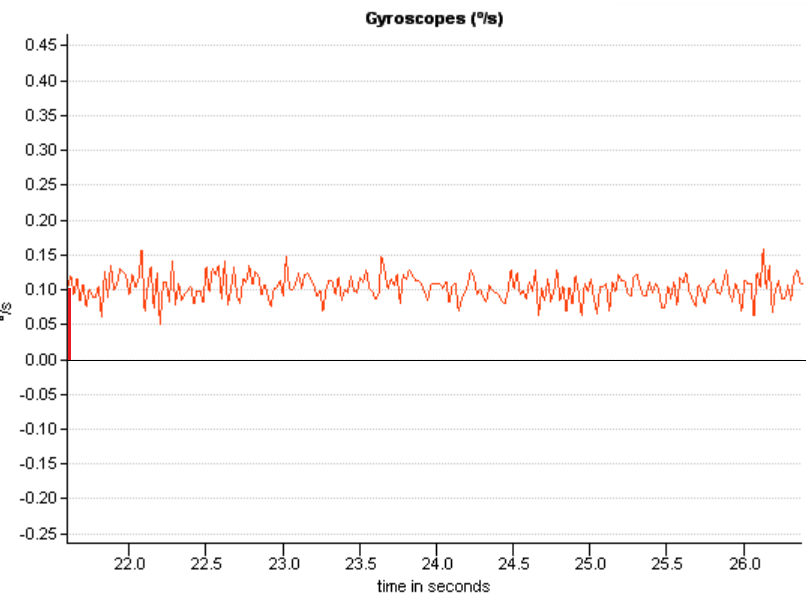
The Velocity Random Walk for accelerometers, or Angular Random Walk for gyroscopes represents the noise of the sensor. While the bias corresponds to the long-term noise, the Random Walk corresponds to the short-term noise. This noise, while integrated, will cause the Random variations of the output.
The Velocity Random Walk is usually expressed in m/s/√hr or m/s/√s or g/√Hz
The Angular Random Walk is usually expressed in °/√hr or °/√s
This is especially important for pointing applications that requires an accurate Roll and Pitch.
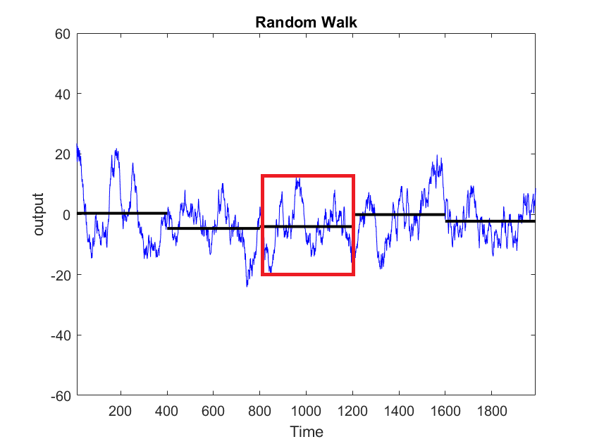
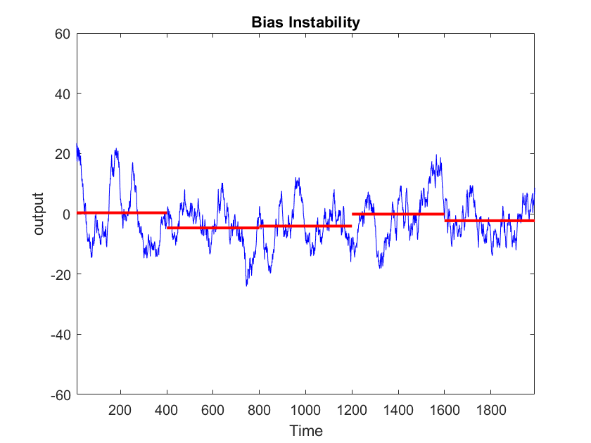
In Run Bias Instability
The bias of an IMU changes over time while powered on, due to various effects such as temperature, and mechanical stress This is why the INS constantly needs to re-estimate this bias with external aiding, such as GNSS, odometer, DVL, etc., combined with vehicle dynamics.
In run Bias instability is a kind of magic number for all MEMS IMUs, with the lower value always being targeted. However, this value doesn't give much insights about the actual sensor performance. Especially because:
- This value is typically measured at constant temperature
- The Bias Instability is never specified with associated time slot (tau). If the bias instability is obtained at very low time slots (for instance tau < 200s), then this information is meaningless because the bias will quickly diverge.
Allan variance
The Allan Variance is a complex diagram, showing for various time scales how good is the sensor.
Allan variance is typically measured at ambient and control temperature so user should still be careful when comparing Allan variances.
When the high frequency noise is "Gaussian", which is typically the case, one can measure the Angular/Velocity random walk at a time scale of 1second.
The Bias Instability is the bottom of the curve.
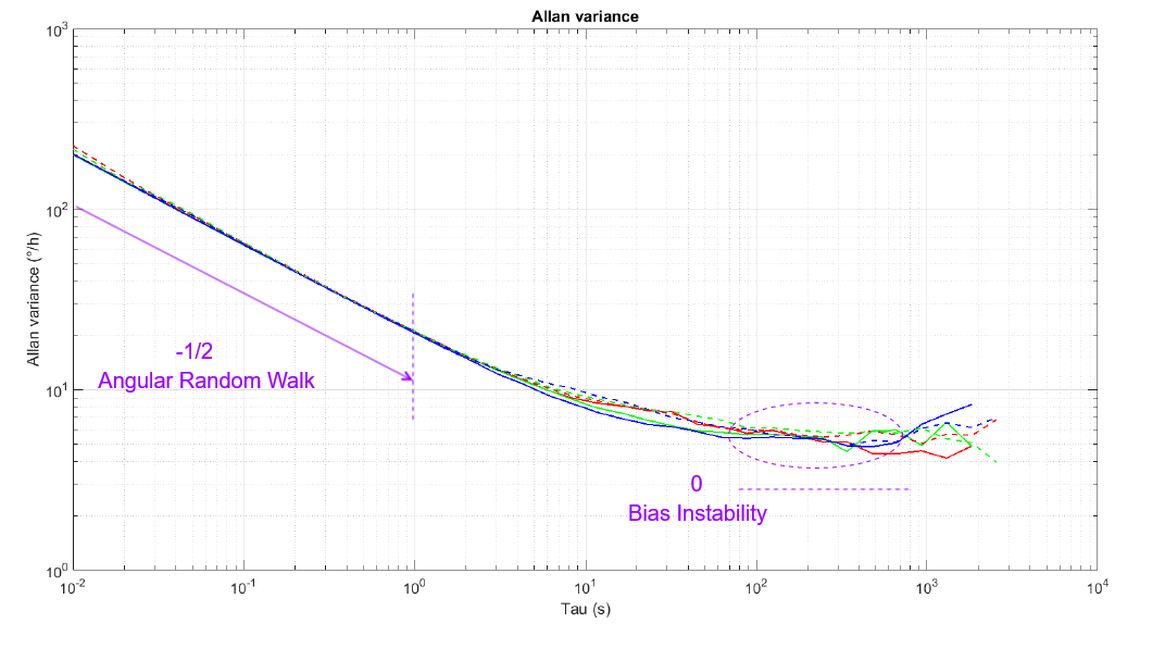
What is more important is how the sensor behave after reaching its bias instability. While the best MEMS sensors will tend to stabilize, lower grade sensors or uncalibrated sensors will quickly ramp up, showing a sensor bias drift.
Vibration Rectification Error
It is generally provided on highly qualified systems, while most IMUs just do not specify what happens in vibrations.
The Vibration Rectification Error gives the expected bias for a given level of vibrations on accelerometers or gyroscopes.
For instance if the VRE is 1 °/h/g² this means we can expect a maximum of 1°/h of bias for 1g of random vibrations.
Sampling Rate
The Sampling Rate is the frequency at which the measurements are taken on the sensor's input. The sampling rate divided by 2 is the Nyquist frequency, which gives the maximum observable frequency of a signal we are measuring.
This parameter matters if we wish to observe higher frequency motions, for instance to achieve vibration monitoring or fast motion compensation.
Bandwidth
The Bandwidth is maximum frequency you can take a reliable acceleration or angular velocity reading. This will directly represent which frequency of motion you will be able to measure, as any signal with a frequency higher than the bandwidth will be attenuated.
This point should be considered for any application that involves vibration or fast motion analysis.
Resolution
The Resolution is the smallest increment measurable on a sensor.
This parameter is of less importance, as usually much lower than the noise of the sensor. The sensor angular or velocity random walk will be the actual decisive factor as this parameter gives the actual system noise level during 1 second averages.
Orthogonality
The Orthogonality represents the physical misalignment between the sensor of different axis.
Cross-Axis Sensitivity
This is the sensitivity of a sensor to a vibrations applied to a perpendicular axle. Ideally it should be minimal as each axle should be independent from each other.
Gyro-G
Gyroscopes can have a bias when under acceleration, this error is called gyro-g effect. This is typically estimated and compensated during calibrations.