Download PDF
Download page Settings block.
Settings block
Description
Defines all the GNSS/INS settings to use such as the IMU error model, the sensor alignment, the GNSS lever arms, and so on. If you have configured a project to import, in the Project block, Qinertia first reads the INS settings from it and then overrides each setting specified in this Settings Block.
Most of the time, if you have correctly setup your SBG Systems INS, you can omit this settings block as Qinertia will read all needed settings from the project acquisition directly. However, most settings are mandatory according to the processing modes and options you would like to use and if Qinertia wasn't able to get settings from the import project, you have to specify them in this block.
You can of course combine both methods and for instance let Qinertia read all settings from your APOGEE acquisition project and then just specify odometer settings because you have manually added odometer measurements from an external ASCII file in the Sources block.
Device Settings Read
Qinertia can read device settings from a project specified in the Project block. However, this is only supported for SBG Systems INS, Novatel SPAN, Septentrio and POS INS format. Please read Input formats for more information.
JSON Block Sample
Full Sample
The following example shows a full settings block to illustrate all configurations. However, it is not practicable in real life applications as it's very unlikely your application have both a DVL and odometer.
"settings": {
  "imu": {
    "id": "apogeeISurfaceV1",
    "referencePoint": [ -0.0004, -0.0011, -0.0865],
    "referencePointFrame": "body",
    "alignment": {
      "rough": ["forward", "right"],
      "fine": [-0.03, 0.01, 0.9],
      "alreadyApplied": true
    },
    "leverArm": [-0.2,0.9,-1.2]
  },
  "outputFrames": [
    {
      "rotation": {
        "rough": ["forward", "right"],
        "fine": [-0.03, 0.01, 0.9]
      },
      "leverArm": [1.0, -0.2, 0.9]
    },
    {
      "rotation": {
        "rough": ["back", "left"],
        "fine": [0, 0, 0]
      },
      "leverArm": [0.1, 0.63, -1.2],
    },
    {
      "rotation": {
        "rough": ["forward", "right"],
        "fine": [0, 0, 0]
      },
      "leverArm": [0, 0, 0],
    }
  ],
  "gnss": {
    "enabled": true,
    "trajectory": {
      "modelId": "septentrio",
      "antenna": {
        "type": "generic",
        "reference": "arp",
        "height": 0,
        "leverArm": [-0.8640, 0.2750, -3.1189]
      },
      "preciseSetup": true
    },
    "raw": {
      "modelId": "septentrio",
      "antenna": {
        "type": "generic",
        "reference": "arp",
        "height": 0,
        "leverArm": [-0.8640, 0.2750, -3.1189]
      },
      "preciseSetup": true
    },
    "trueHeading": {
      "modelId": "septentrio",
      "mode": "dualManual",
      "antenna": {
        "type": "generic",
        "reference": "arp",
        "height": 0,
        "leverArm": [-0.8640, 0.2750, -3.1189],
        "secondaryLeverArm": [1.1380, 0.2770, -3.1399]
      },
      "preciseSetup": true
    }
  },
  "odometer": {
    "enabled": true,
    "modelId": "default",
    "accuracy": 100,
    "gain": 1,
    "reversed": false,
    "leverArm": [0.5, -0.9, 1.3],
    "preciseSetup": true
  },
  "dvl": {
    "enabled": true,
    "modelId": "default",
    "alignment": {
      "rough": ["forward", "right"],
      "fine": [0.1,-0.2,0.9]
    },
    "leverArm": [-0.8, 0.11, 1.2],
    "preciseSetup": true
  }
}GNSS only sample
This is the minimal block if you would like to process.
"settings": {
  "gnss": {
    "raw": {
      "modelId": "auto",
      "antenna": {
        "type": "TWIVSP6037L     NONE",
        "reference": "arp"
      }
    }
  }
}Custom antenna model
If you use a custom antenna that is not available in Qinertia antenna database, you can define your own antenna offsets in centimeter as shown in the example below:
"settings": {
  "gnss": {
    "raw": {
      "modelId": "auto",
      "antenna": {
        "type": "custom",
        "offsets": {
          "l1": 5.61,
          "l2": 4.96
        },
        "reference": "arp"
      }
    }
  }
}Settings override sample
The following block consider an APOGEE that is correctly setup so Qinertia is able to read all the INS settings. Unfortunately during the installation, the secondary GNSS lever arm was not correctly entered.
The settings block below is used to override the faulty dual antenna parameters with the correct lever arm values.
"settings": {
  "gnss": {
    "trueHeading": {
      "modelId": "septentrio",
      "mode": "dualManual",
      "antenna": {
        "type": "TWIVSP6037L     NONE",
        "reference": "arp",
        "height": 0,
        "leverArm": [-0.8640, 0.2750, -3.1189],
        "secondaryLeverArm": [1.1380, 0.2770, -3.1399]
      },
      "preciseSetup": true
    }
  }
}Block Specification
This is the main settings block object, you can configure the IMU and each aiding module such as GNSS, odometer, etc
| Parameter | Type | Optional | Description |
|---|---|---|---|
imu | object | Inertial Measurement Unit settings such as the error model to use. If Qinertia wasn't able to read these settings from a project and you don't include this block, you will only be able to process GNSS only solutions. Please see the IMU Sub block. | |
outputFrames | array | Define up to three user output frames composed of an alignment and a lever arm. It is used to output/export INS data at a specific location with a user defined frame rotation. Please see the Output Frame Sub Block | |
gnss | object | GNSS aiding settings for each type of GNSS input:
This block is mandatory if Qinertia was not able to read GNSS aiding settings from an imported project. Please see the GNSS Sub block. | |
odometer | object | Odometer or DMI velocity aiding settings for ground applications. If Qinertia was not able to read these settings from a project and you don't include this block, the odometer aiding will be disabled. Please see the Odometer Sub block. | |
dvl | object | Doppler Velocity Logger (DVL) aiding settings for marine applications. If Qinertia was not able to read these settings from a project and you don't include this block, the DVL aiding will be disabled. Please see the DVL Sub block. |
IMU Sub block
Configure the IMU error model and how the IMU is installed within the vehicle. This bock is only relevant for INS processing and not for GNSS only modes.
| Parameter | Type | Optional | Description |
|---|---|---|---|
| enum | Specify which IMU model to use for the processing as listed in the page IMU Models This parameter is mandatory if Qinertia wasn't able to read it from an imported project. | |
| array or string | X, Y, Z vector from the IMU physical measurement point to the reference point or a reference point id as listed in the IMU model:
All lever arms such as GNSS antennas are measured from the reference point. The INS data are also output at this reference point. If not specified, a default 0,0,0 offset is used. | |
| enum | Defines in which frame the reference point vector is expressed:
| |
| array | X, Y, Z INS primary lever arm vector in meters. This is generally used to input the COG (Center of Gravity or Center of Rotation) point. If not specified, a default 0,0,0 lever arm is used. | |
| array | Define the rough (axis) IMU alignment in the vehicle frame. This parameter is an array of two keys one for the X axis direction and one for the Y axis direction. The Z axis direction is indeed automatically computed from X/Y directions to represented a right handled coordinate frame. Please refer to Rough Alignment Values section to get the list of available options. If not specified, the default | |
| array | Specify any roll, pitch and yaw fine alignment between the IMU frame and the vehicle frame. The angles are expressed in degrees and follow SBG Systems conventions. If not specified no fine alignment is applied. | |
| boolean | Set to true if the alignment specified above has already been applied on the input IMU data. In this case, Qinertia will not rotate IMU data before processing the log. This parameter is helpful if you would like to change the alignment afterward directly in Qinertia. Qinertia will indeed be able to remove any already applied alignment on the IMU data to then apply the new alignment. If not specified, this parameter is set to |
Alignment
You can define the IMU alignment using only roll, pitch and yaw angles in the alignment.fine parameter. In this case simply omit the alignment.rough parameter or set it to ["forward", "right"]
Output Frame Sub Block
This block represents a user defined output frame that is composed of a frame rotation (alignment) and a lever arm to deport the measurements at a specific location. In Qinertia export module, you can select which output frame to use within this list.
| Parameter | Type | Optional | Description |
|---|---|---|---|
rotation.rough | array | Apply a rough (axis) frame rotation. You specify the X and Z axis directions and Qinertia computes automatically the Z axis direction to get a valid right handled coordinate frame. Please refer to Rough Alignment Values section to get the list of available options. If not specified, the default | |
rotation.fine | array | Specify any roll, pitch and yaw additional rotation to apply. The angles are expressed in degrees and follow SBG Systems conventions. If not specified no additional fine rotation is applied. | |
| array | X, Y, Z lever arm in meters to deport measurements to. It is expressed in the vehicle frame before the above rotation is applied. If not specified, a default 0,0,0 lever arm is used. |
Alignment
You can define the rotation using only roll, pitch and yaw angles in the rotation.fine parameter. In this case simply omit the rotation.rough parameter or set it to ["forward", "right"]
GNSS Sub block
You can setup the GNSS aiding that is used for all processing modes. The GNSS aiding is composed of three aiding inputs that are trajectory, raw and true heading. Each aiding input has it's own configuration such as the GNSS error model and the lever arms.
Most of the time the three aiding inputs share the same settings. It is the case, for example, when the three measurements come from the same GNSS receiver. However, to offer maximum flexibility, Qinertia lets you enter specific settings for each aiding input.
For example, you can have a GNSS receiver that provides the trajectory (real time PVT data), an other one that outputs the GNSS raw data and a third one that just provides dual antenna true heading information. In this situation, you would like to configure each GNSS error model, lever arm and antenna separately.
GNSS only
Only the raw sub block is applicable for GNSS only computations. Trajectory and true heading are only used for INS processing.
| Parameter | Type | Optional | Description |
|---|---|---|---|
| boolean | Set to true to enable the GNSS module or false if you don't want Qinertia to use GNSS at all. If not specified, this parameter is set to | |
| string | GNSS error model to use for loosely coupling INS processing:
If not specified, the | |
| object | Configure the GNSS antenna and lever arm for loosely coupling processing. See antenna block below. This parameter is mandatory if Qinertia wasn't able to read it from an imported project and you would like to compute a loosely coupled INS solution. | |
| boolean | Set to true if trajectory GNSS lever arm setup should be considered to be precise. In this case, Qinertia will not try to estimate and refine automatically the main GNSS lever arm in loosely coupling INS processing. If not specified, this parameter is set to | |
| string | GNSS error model to use for tightly coupled INS or GNSS only processing:
If not specified, the | |
| object | Configure the GNSS antenna and lever arm for tightly coupled processing. See antenna block below. This parameter is mandatory if Qinertia wasn't able to read it from an imported project and you would like to compute a tightly coupled INS solution. | |
| boolean | Set to true if RAW GNSS lever arm setup should be considered to be precise. In this case, Qinertia will not try to estimate and refine automatically the main GNSS lever arm in tightly coupled INS processing. If not specified, this parameter is set to | |
| string | GNSS error model to use for dual antenna heading integration in INS processing:
If not specified, the | |
| enum | Specify if the dual antenna lever arm is known or should be estimated:
If not specified, the | |
| object | Configure the GNSS antenna and dual antenna alignment/lever arms for INS processing. See antenna block below. This parameter is mandatory if Qinertia wasn't able to read it from an imported project and you would like to compute an INS solution. | |
| boolean | Set to true if dual antenna alignment/lever arms should be considered to be precise. In this case, Qinertia will not try to estimate and refine the dual antenna alignment during INS processing. This parameter has to be set to true if the If not specified, this parameter is set to |
GNSS Antenna block
Enter the GNSS antenna type and associated lever arms.
| Parameter | Type | Optional | Description |
|---|---|---|---|
| string | Antenna ANTEX identifier that can ovverides the one read from the GNSS data. The valid options are:
If not specified, the default | |
antenna.offsets.l1 | number | Define the ARP to L1 phase center vertical offset in centimeter for GPS signals. This field is applicable and mandatory only if | |
antenna.offsets.l2 | number | Define the ARP to L2 phase center vertical offset in centimeter for GPS signals. This field is applicable and mandatory only if If you don't know the L2 offset, it's generally a good idea to use the same value as L1. | |
| enum | Select where the GNSS lever arm is referenced:
If not specified, the default | |
| number | Antenna height in meters to apply between the reference point and the arp/apc point. You can use this setting to apply an addition offset in the Z axis and expressed in the the vehicle frame for INS projects. If not specified, no offset is applied. | |
| array | Primary X,Y,Z lever arm in meters from the INS to the GNSS antenna. This parameter is mandatory if Qinertia wasn't able to read it from an imported project and you would like to compute an INS solution. For GNSS only, this parameter is optional and will apply a NED offset rather than a XYZ one. | |
| array | Secondary X,Y,Z lever arm in meters from the INS to the GNSS antenna. This parameter is only applicable for This parameter is mandatory if Qinertia wasn't able to read it from an imported project and you would like to compute an INS solution with |
External Trajectory & Heading
If you would like to input an external trajectory in Qinertia, you should use the gnss.trajectory settings. It is the same for external heading updates. Even if these inputs don't come from a GNSS receiver, Qinertia will process them correctly. Just make sure you use the default GNSS error model.
Odometer Sub block
You can optionally setup odometer (DMI) velocity aiding for ground based applications.
| Parameter | Type | Optional | Description |
|---|---|---|---|
| boolean | Set to true to enable the odometer module or false if you don't want Qinertia to use odometer velocity aiding at all. If not specified, this parameter is set to | |
| string | Select the odometer error model to use by the INS filter. Always set to | |
| array | X,Y,Z lever arm in meters from the vehicle frame to the odometer. If not specified, a default 0,0,0 lever arm is used. | |
preciseSetup | boolean | Set to true if odometer mechanical setup should be considered as precise. In this case, Qinertia will not try to estimate and refine automatically the odometer lever arm parameter. If not specified, this parameter is set to | |
gain | number | Odometer scale factory to apply on raw measurements. Each odometer velocity will be multiplied by this scale factor. If not specified, this parameter is set to 1.0 | |
| number | Enter the odometer gain accuracy in percent from 1 to 1000%. An accuracy of 1% means the odometer scale factor is very accurate and shouldn't be refined too much by Qinertia. An accuracy of 100% means Qinertia consider you the gain can be up to 2 times higher or smaller and Qinertia has to estimate it. Most of the time, it is recommended to use a 1000% accuracy and let Qinertia estimate the gain as it's very efficient as soon as you have regions with good GNSS availability. If not specified, this parameter is set to 1000%. | |
| boolean | Set to true if measurements are reversed. If not specified, this parameter is set to |
DVL Sub block
You can optionally setup DVL velocity aiding for marine applications.
| Parameter | Type | Optional | Description |
|---|---|---|---|
| boolean | Set to true to enable the DVL aiding module or false if you don't want Qinertia to use DVL velocity aiding at all. If not specified, this parameter is set to | |
| string | Select the DVL error model to use by the INS filter. Always set to | |
| array | Define the rough (axis) DVL alignment in the vehicle frame. This parameter is an array of two keys one for the X axis direction and one for the Y axis direction. The Z axis direction is indeed automatically computed from X/Y directions to represented a right handled coordinate frame. Please refer to Rough Alignment Values section to get the list of available options. If not specified, the default | |
| array | Specify any roll, pitch and yaw fine miss-alignment from the vehicle frame to the DVL frame. The angles are expressed in degrees and follow SBG Systems conventions. If not specified no fine alignment is applied. | |
| array | X,Y,Z lever arm in meters from the vehicle frame to the DVL. If not specified, a default 0,0,0 lever arm is used. | |
| boolean | Set to true if DVL mechanical setup should be considered as precise. In this case, Qinertia will not try to estimate and refine automatically the alignment and lever arm parameters. If not specified, this parameter is set to |
Alignment
You can define the DVL alignment using only roll, pitch and yaw angles in the alignment.fine parameter. In this case simply omit the alignment.rough parameter or set it to ["forward", "right"]
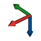
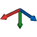
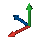
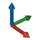
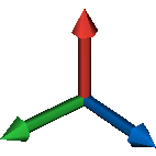
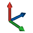
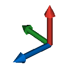
Rough Alignment Values
Please find below the list of all valid X and Y rough alignment values. The Z axis orientation is automatically computed based on the input X and Y values.
| Frame | Values | Description |
|---|---|---|
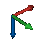
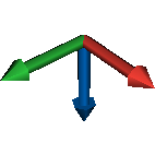
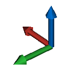
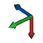
| rough: ["forward", "right"] |
|
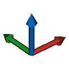
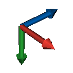
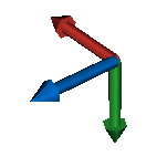
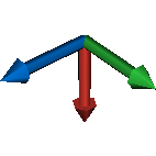
| rough: ["forward", "left"] |
|
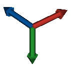
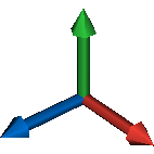
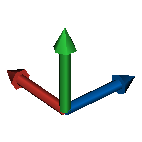
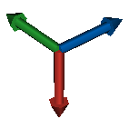
| rough: ["forward", "down"] |
|
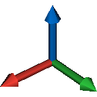
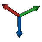
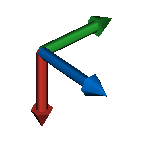
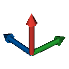
| rough: ["forward", "up"] |
|
| rough: ["backward", "right"] |
|
| rough: ["backward", "left"] |
|
|
|
|
| rough: ["backward", "up"] |
|
| rough: ["right", "forward"] |
|
| rough: ["right", "backward"] |
|
| rough: ["right", "down"] |
|
| rough: ["right", "up"] |
|
| rough: ["left", "forward"] |
|
| rough: ["left", "backward"] |
|
| rough: ["left", "down"] |
|
| rough: ["left", "up"] |
|
| rough: ["down", "forward"] |
|
| rough: ["down", "backward"] |
|
| rough: ["down", "right"] |
|
|
|
|
| rough: ["up", "forward"] |
|
| rough: ["up", "backward"] |
|
| rough: ["up", "right"] |
|
| rough: ["up", "left"] |
|