This tutorial will show you what to expect on receiving first Ellipse OEM products from SBG systems, where to find available software and manuals, and how to perform the initial connections.
OEM version communicating via TTL signal, the development kit allows to simplify the use of OEM ellipse modules as it gives an access to all communication ports via several protocols (USB, CAN, RS232, UART).
Downloading the sbgCenter Application
The latest sbgCenter Application can be installed and can be used to configure and monitor the Ellipse. We recommend to get familiar with configuring the Ellipse this way before looking into configuring it using the sbgECom commands.
Documentation and Resources
This center provides access to all the documentation you might need during your product evaluation and integration:
You can find the documentation and resources for Ellipse such as hardware manual, mechanical drawings in the Product documentation section.
On this link you will find the Operating Handbooks and external aiding integration guides.
You can also find the Firmware manual and sbgECom, as well as all Firmware releases and change notes.
Hardware Connection
Ellipse OEM V3 Development Kit
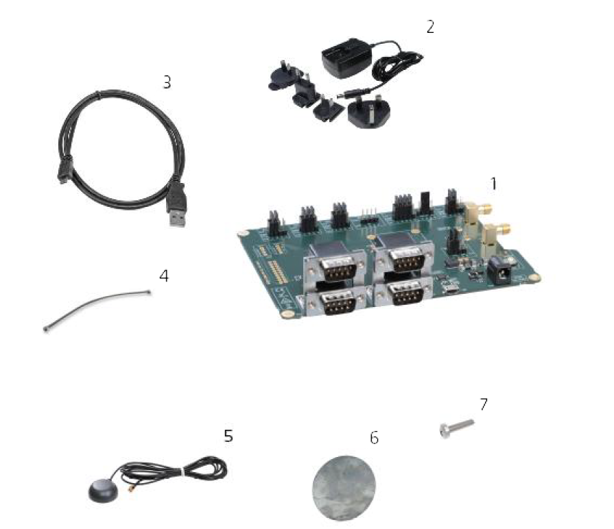
It comes in a package with the following components :
- Development Board for ELLIPSE OEM
- Power supply
- USB Cable
- Coax Cable U.FL to U.FL
- Dual band GNSS patch antennas (depending of Ellipse model)
- Ground plane for patch antenna (depending of Ellipse model)
- Screw Philips
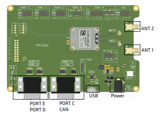
The drawing board below describes connections available on the development board:
The picture below shows the Ellipse-D OEM installed on the development board with accessories connected.
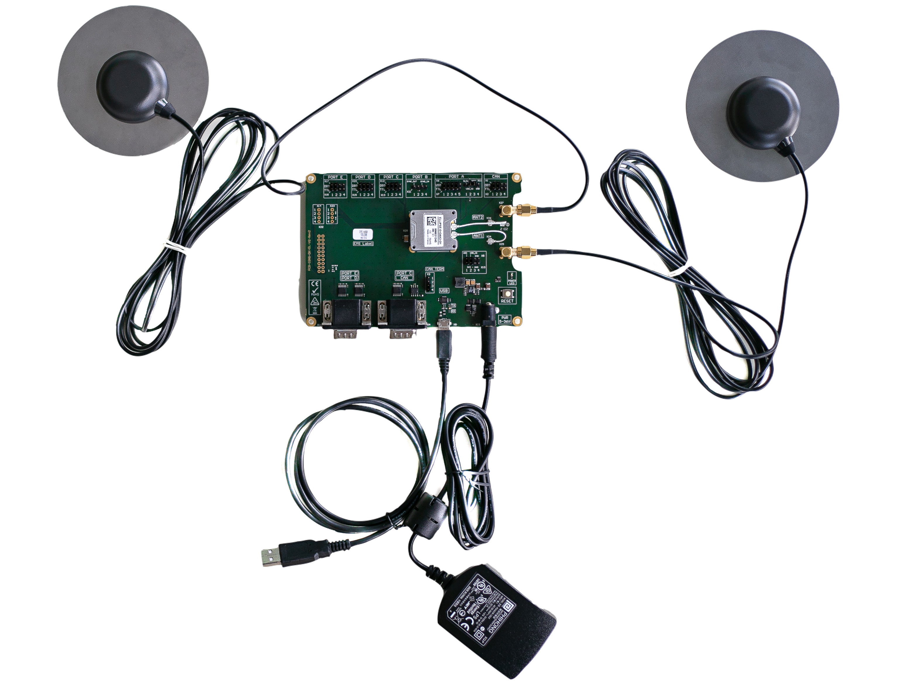
The USB cable (Serial to USB converter) shown in the component list #3 provides serial communication to port A of the sensor and is used to connect the system to a computer in order configure it with sbgCenter.
sbgCenter
The Configuration using sbgCenter manual will guide you through detailed steps to configure an Ellipse using this tool.
Opening sbgCenter
Double-click the sbgCenter icon on your desktop  .
.
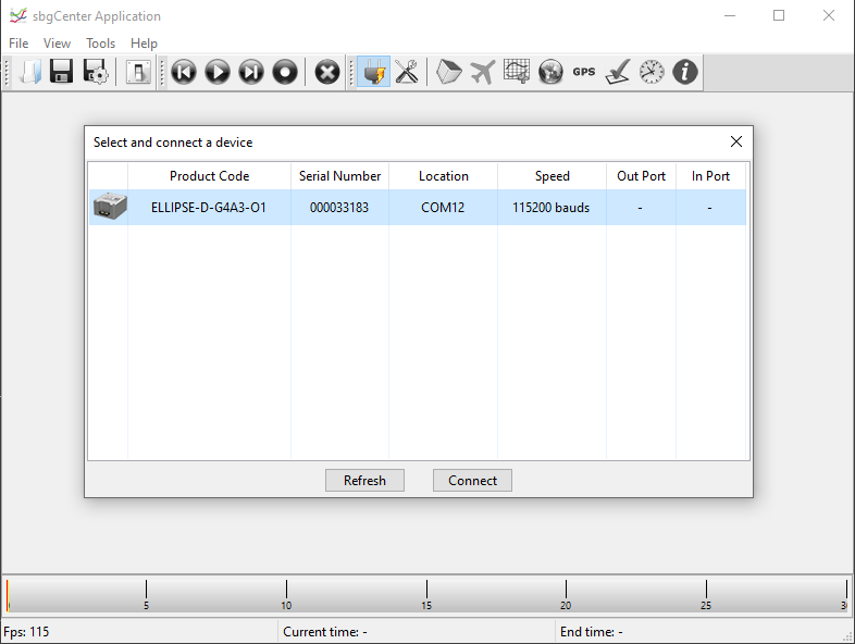
Click on the icon  . A window will appear to list the attached device.
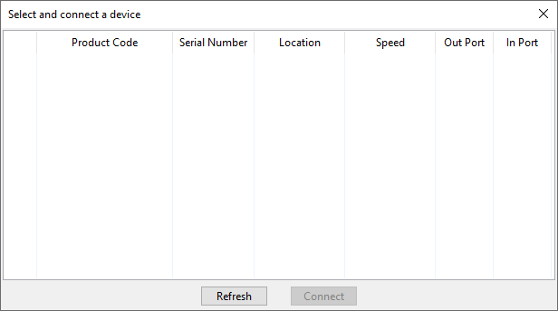
Click on the Refresh button.
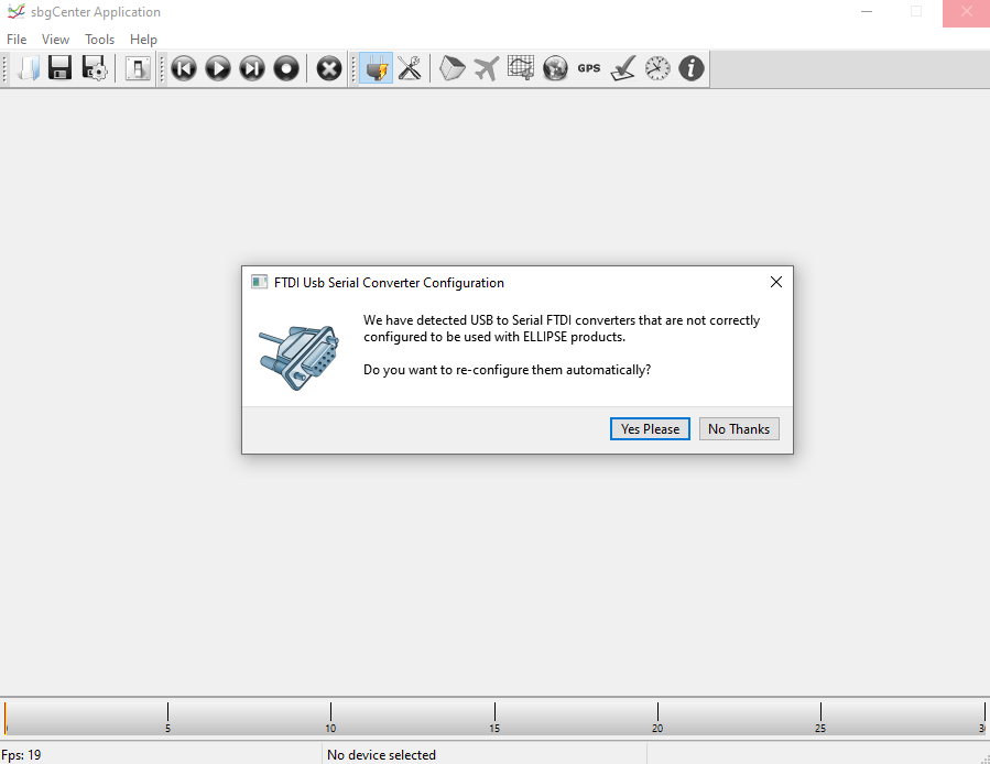
If this is the first time that you connect an Ellipse to your computer, the window below will appear, asking you to change the FTDI USB serial converter configuration. Click “Yes Please” to ensure proper operation and then click "Refresh" again to update the device list.
Your Ellipse should be listed now on the available devices. Click the “Connect” button to start using the sensor.
Configuration Page
You can now navigate through each setting page by using the tabs on the left. In order to configure, click on the toolbox on top of the interface to open the configuration window.
A default factory setup is configured, we advise you follow the menu from top to bottom to configure your device for your application (visit the Operating Handbooks section to find recommended configuration).

Display
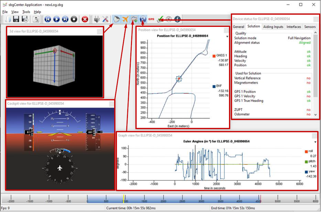
The sbgCenter provides a wide range of displays to visualize your sensor data such as 3D Cube or Cockpit view for orientation display, 2D Map, Time series graphs, GNSS data, Device status, UTC Time & data, and more.