Download PDF
Download page CAN bus and outputs.
CAN bus and outputs
The CAN implementation supports both CAN 2.0A and CAN 2.0B standards in a very versatile manner. It has been designed to maximize the compatibility with third party equipment and CAN software. This guide will show you how to use the Ellipse CAN output.
Physical installation
Wiring considerations for CAN bus use
The use of the Ellipse for CAN outputs requires one of these cables:
- CA-ELI-SPLIT-CAN-DB-0.5M
- CA-ELI-RS232-CAN-3M
Configuration
The configuration of the Ellipse is always made via the serial port (COM Port A) in RS232 or RS422, not via CAN.
The CAN Bus typical wiring
SBG Systems products are designed to follow the ISO 11898 standard which defines the following specification for the CAN bus:
- a maximum output rate of 1 Mbps for a CAN bus length of 40m (backbone), and with a maximum of 30 nodes.
- backbone of the CAN bus should be a single line consisting in a twisted pair terminated at each end with 120 Ω resistor to prevent signal reflections.
- a maximum of 0.3m is recommended for each stub length (extension from the CAN bus backbone where a node is connected).
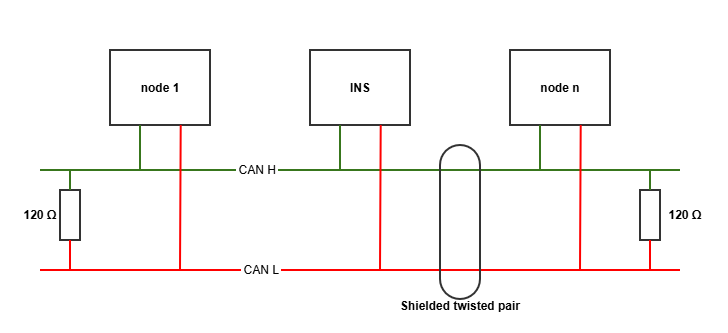
CAN termination resistor
The SBG Systems products don't have an internal termination resistor on the CAN port.
CAN Bus configuration with sbgCenter application
Step 1: Input/Output
The Following view is accessible in sbgCenter, after selecting the configuration icon and go to the Input/Output tab.
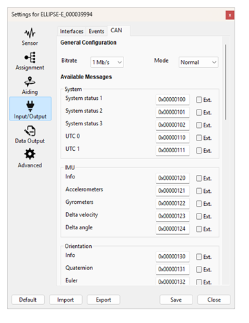
By default, the CAN bus is disabled. The bus mode and a bitrate must be set to enable this bus.
The mode options are:
Mode | Description |
|---|---|
Disabled | The CAN bus is set to off |
Listen only | The CAN bus is set as an input. This option is only used for CAN odometry |
Normal | The CAN bus transmits and receives data |
Once enabled, the messages identifier can be changed (beware to keep it unique within your system to avoid collisions).
Default identifiers
Changing the messages default identifiers will break its compatibility with the .dbc and .dbf files provided by SBG Systems.
Step 2: Data Output
After configuring the CAN Bus in the Input/Output tab, the data output section will allow you to define each message output rate.
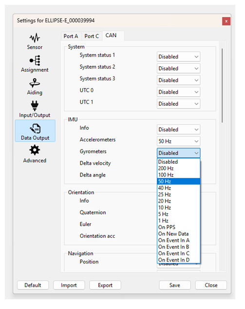
The definition of each CAN message can be found in our Firmware documentation.
sbgCan.dbc and sbgCan.dbf files can be found in the can folder of our sbgEcom GitHub page.
CAN Bus Status
Some status are available to monitor the proper functioning of the CAN bus. They are part of the messages that are output, and can be seen in the sbgCenter too.
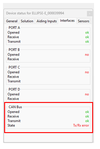
CAN status description
Status | State | Description |
|---|---|---|
Opened | ok | Working properly |
no | CAN disabled | |
Receive | ok | Working properly |
no | Saturation on CAN bus input buffer | |
Transmit | ok | Working properly |
no | Saturation on CAN bus output buffer | |
State | ok | The CAN bus is working correctly |
Tx/ Rx error | Transmit or receive error (or no CAN bus connected) | |
error | A general error has occurred on the CAN bus | |
Bus off | Bus off operation due to too many errors |