Download PDF
Download page First connection to Ellipse OEM.
First connection to Ellipse OEM
This tutorial will guide you in your first connection with the Ellipse OEM. It will first provide instructions on where to find our free software tools and walk you through the steps to successfully perform your first connection with the ELLIPSE.
The OEM version communicates via TTL signals. The development kit simplifies the use of ELLIPSE OEM modules as it gives an access to all communication ports via multiple protocols (USB, CAN, RS232, UART).
Register your ELLIPSE in MySBG
For detailed, step-by-step instructions on creating a MySBG account, please refer to the first section of this link
- Visit https://my.sbg-systems.com/
- Click on "add" in "products" section
- You can visualize the "validation report"
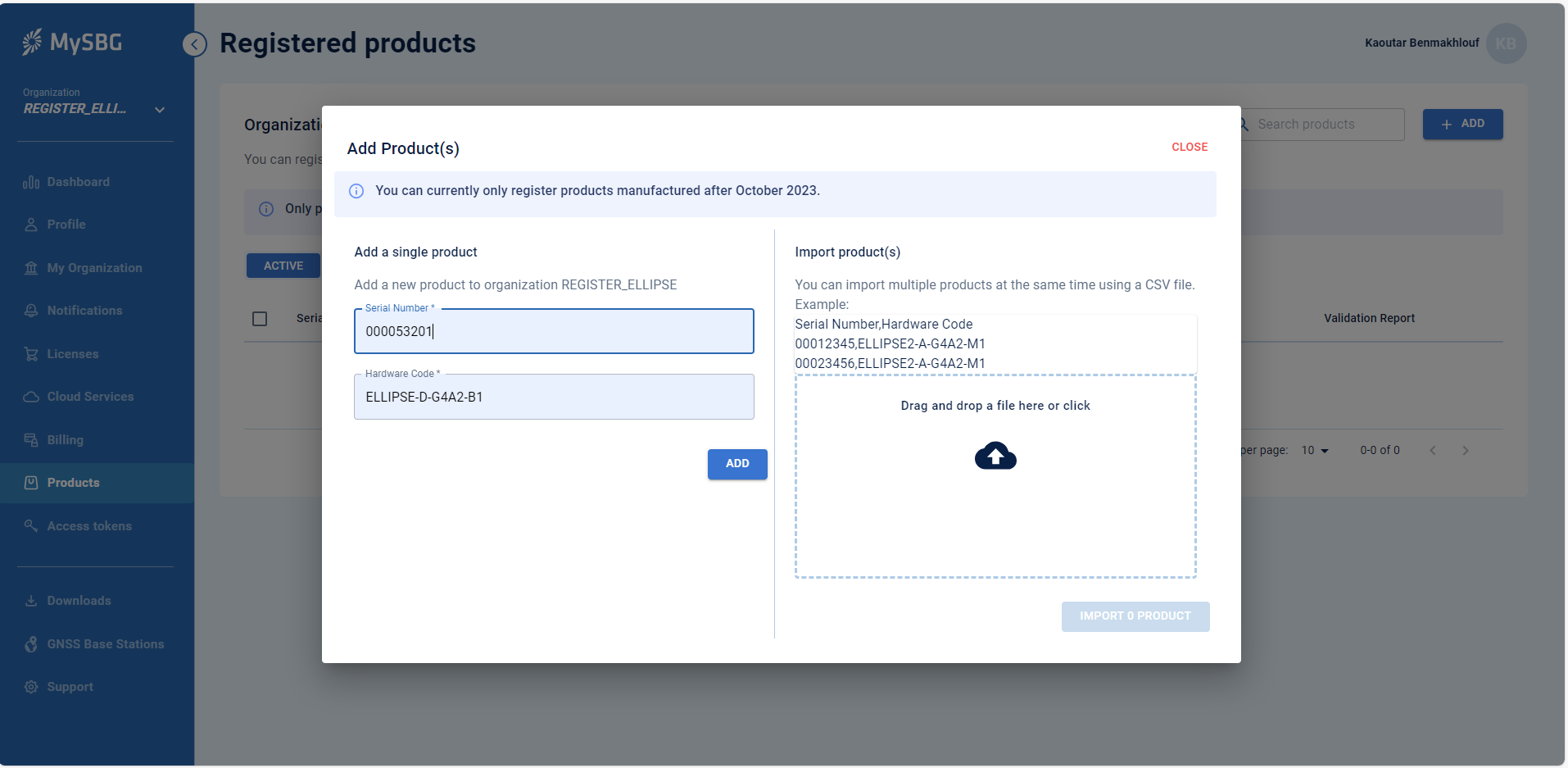
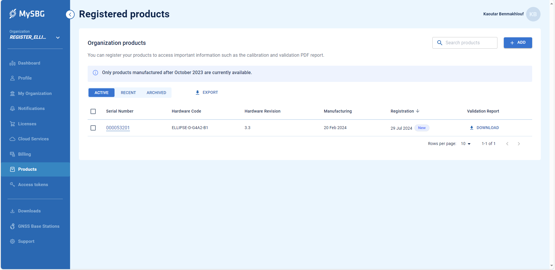
Only products manufactured after October 2023 are available on MySBG.
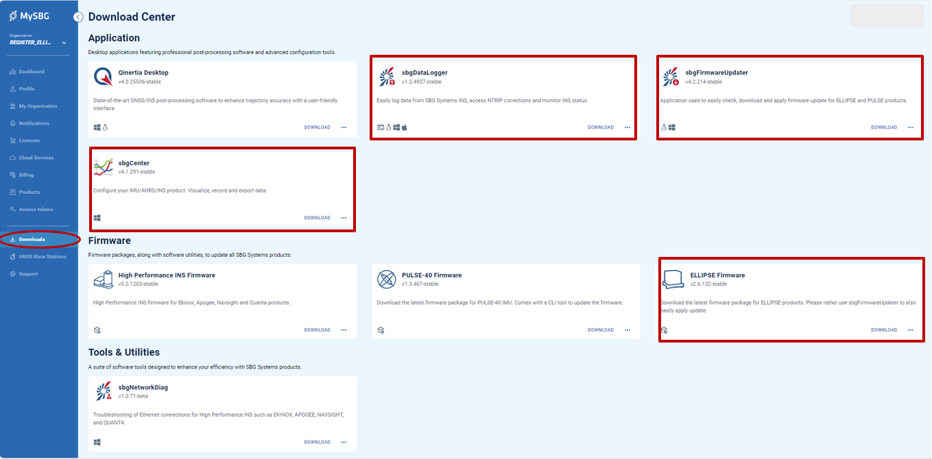
Software tools at the Download Center
All the software tools you need can be downloaded from your MySBG account. For the ELLIPSE, you should download:
- sbgCenter: tool to establish your first connection and configure the ELLIPSE
- sbgDataLogger: tool to easily log ELLIPSE data and forward RTCM corrections to the unit
- sbgFirmwareUpdater: tool to update the firmware version of your ELLIPSE and benefit from the latest improvements
- ELLIPSE firmware : download the latest firmware package for ELLIPSE
Documentation and Resources
This center provides access to all the documentation you might need during your product evaluation and integration:
- All the documentation related to the product such as hardware manual, mechanical drawings can be found in the Product documentation section
- On this link you will find the guides and best practices on how to configure the ELLIPSE for specific operations
- You can also find the Firmware manual and sbgECom, as well as all Firmware releases and change notes
Hardware Connection
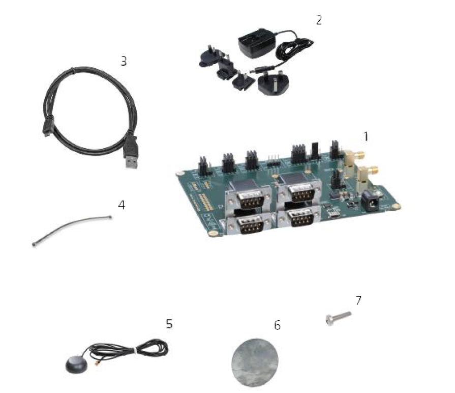
ELLIPSE OEM V3 Development Kit
The ELLIPSE OEM comes in a package with the following components :
- Development Board for ELLIPSE OEM
- Power supply
- USB Cable
- U.FL to U.FL coax Cable
- Dual-band GNSS patch antennas (depending on ELLIPSE model)
- Ground plane for patch antenna (depending on ELLIPSE model)
- Screw Philips
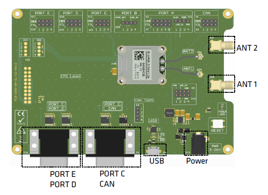
The drawing board below describes connections available on the development board:
The picture below shows the ELLIPSE-D OEM installed on the development board with accessories connected.
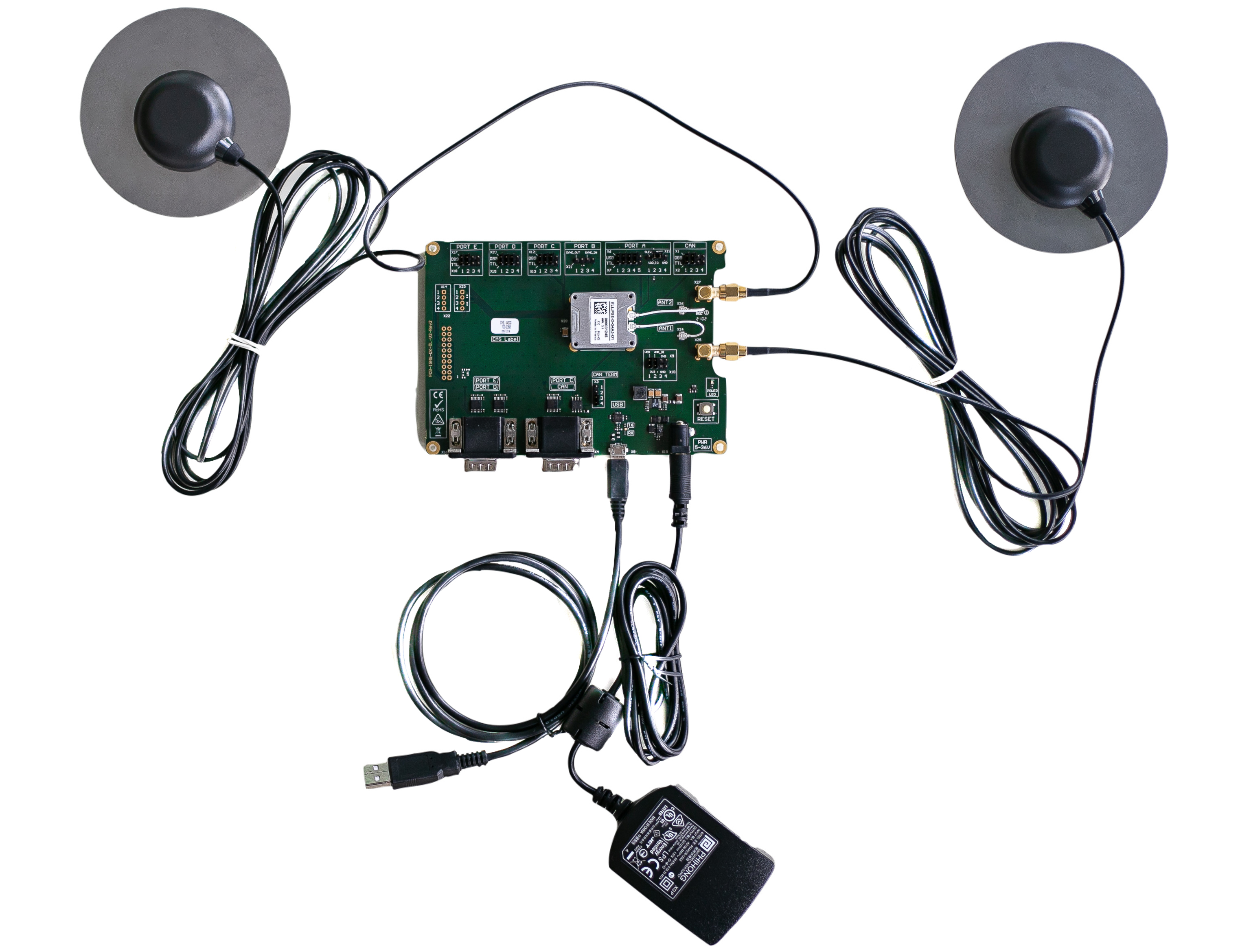
The USB cable (Serial to USB converter) shown in the component list #3 provides serial communication to port A of the sensor and is used to connect the system to a computer in order configure it with sbgCenter.
sbgCenter software
There are comprehensive guides that you can find about using sbgCenter in the General configuration space. The most useful document for starters is the Configuration using sbgCenter manual that will guide you through detailed steps to configure an Ellipse using this tool.
Opening sbgCenter
Double-click the sbgCenter icon on your desktop ![]() .
.
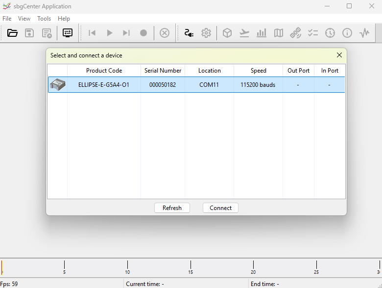
Click on the icon ![]() . A window will appear to list the attached device.
. A window will appear to list the attached device.
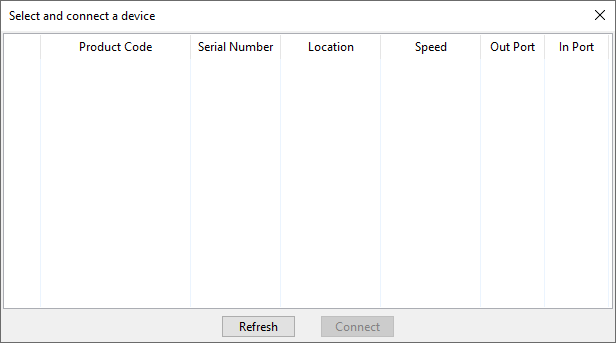
Click on the Refresh button.
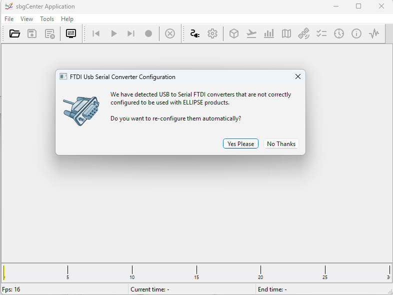
If this is the first time that you connect an Ellipse to your computer, the window below will appear, asking you to change the FTDI USB serial converter configuration. Click “Yes Please” to ensure proper operation and then click "Refresh" again to update the device list.
Your Ellipse should be listed now on the available devices. Click the “Connect” button to start using the sensor.
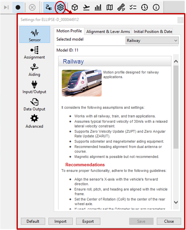
Configuration Page
You can now navigate through each setting page by using the tabs on the left. In order to configure, click on the toolbox on top of the interface to open the configuration window.
A default factory setup is configured, we advise you follow the menu from top to bottom to configure your device for your application (visit the Operating Handbooks section to find recommended configuration).
Display
The sbgCenter provides a wide range of displays to visualize your sensor data such as 3D Cube or Cockpit view for orientation display, 2D Map, Time series graphs, GNSS data, Device status, UTC Time & data, and more.