Download PDF
Download page Generic Velocity Integration.
Generic Velocity Integration
Data Format
In order to be compatible with our product, the Generic Velocity aiding must be input in the sbgECom format. The INS utilizes 1D, 2D, or 3D velocity input expressed in m/s in the instrument body frame.

A standard deviation must be provided for each input velocity component. Note that these values are used at face value within a basic error model, meaning inaccurate standard deviations may lead to navigation issues.
To achieve optimal performance, you can either attempt to tune your own standard deviations or have SBG Systems develop the error model with you.
The SBG_ECOM_LOG_VELOCITY_1 (58) message is described in firmware documentation.
Mechanical Installation
The velocity sensor must be rigidly fixed to the vehicle frame to avoid any relative motion with the INS. Additionally, ensure the sensor is placed away from environmental disturbances, such as boundary layer turbulence for air and water applications or high-vibration areas for optical sensors.
The Lever Arm, expressed in the vehicle coordinate frame (vehicle reference with X forward, Y to the right, and Z down) from the SBG INS reference point to the velocity sensor’s measurement point, must be measured with at least 5cm accuracy.
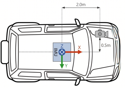
Lever Arm example
If the sensor is not perfectly aligned with the vehicle frame, the misalignment angles must be configured in the software as explained in the Accounting for misalignment article.
Electrical Installation
Data input connection
Regarding the data input, a simple serial connection is generally used, by connecting the Generic Velocity computer serial port to one of the SBG INS available serial ports (eg. PORT B Rx), either in RS-232 or in RS-422.
Synchronization between Generic Velocity and INS
When used as an input, the TIME_STAMP field of the message may either represent an absolute time of validity or a measurement delay, depending on the status flags. The measurement delay allows the INS to calculate an absolute timestamp based on the reception time, and the specified delay. See the Data Format section above for more information on the format.

The system is highly robust against data latency. The INS can effectively handle and process measurement delays of multiple seconds while maintaining an accurate navigation solution.
Software Configuration
Aiding Assignment
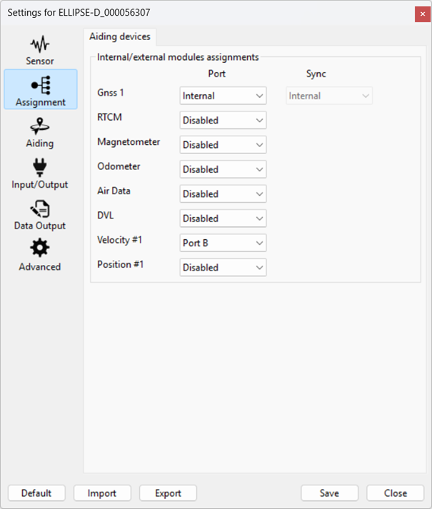
Once a motion profile is selected, you can activate Velocity #1 by selecting a dedicated source.
Aiding Settings
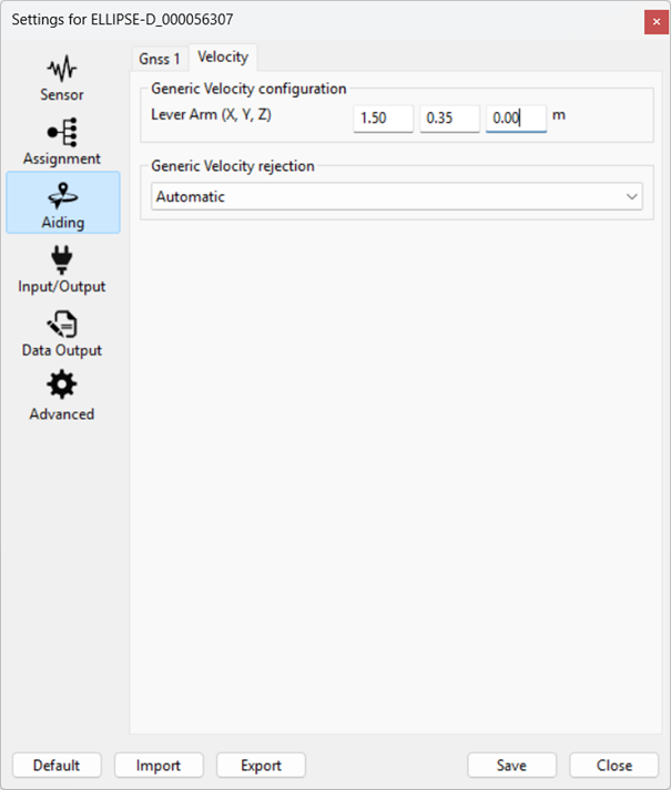
Then you can configure the Lever Arm of the Generic Velocity sensor (expressed in the vehicle reference frame from the SBG INS reference point to the velocity sensor’s measurement point).
The Aiding rejection Automatic is advised so the Kalman filter determines the confidence of this parameter by itself.
If the axis of the Generic Velocity sensor cannot be aligned with the reference frame of the vehicle, you must enter the Misalignment for the rough misalignment and the fine misalignment. This is done using using the Configuration API (sbgInsRestApi). A simple way to use this API on a Windows/Linux/Mac OS X computer is to use the command line tool sbgEcomApi.exe, provided on GitHub, via port A.
This can be done using the API commands below for example.
sbgEComApi.exe -s <COM> -r <baudrate> /api/v1/settings/aiding/vel1/alignment/rough -p -b [\"backward\",\"left\"]
sbgEComApi.exe -s <COM> -r <baudrate> /api/v1/settings/aiding/vel1/alignment/fine -p -b [1,2,3]
Input / Output
COM Ports
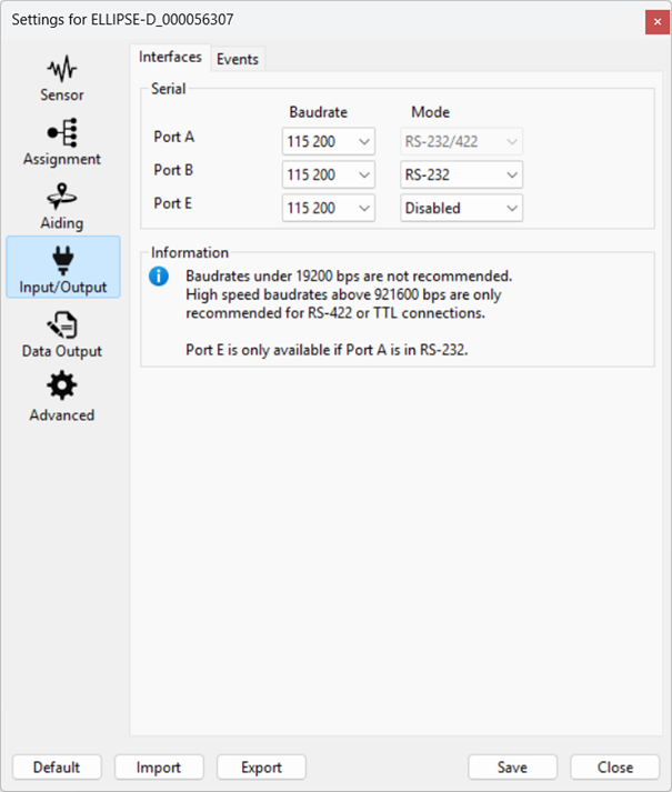
Selected communication port needs to be configured in accordance to your Generic Velocity source.
Data Output
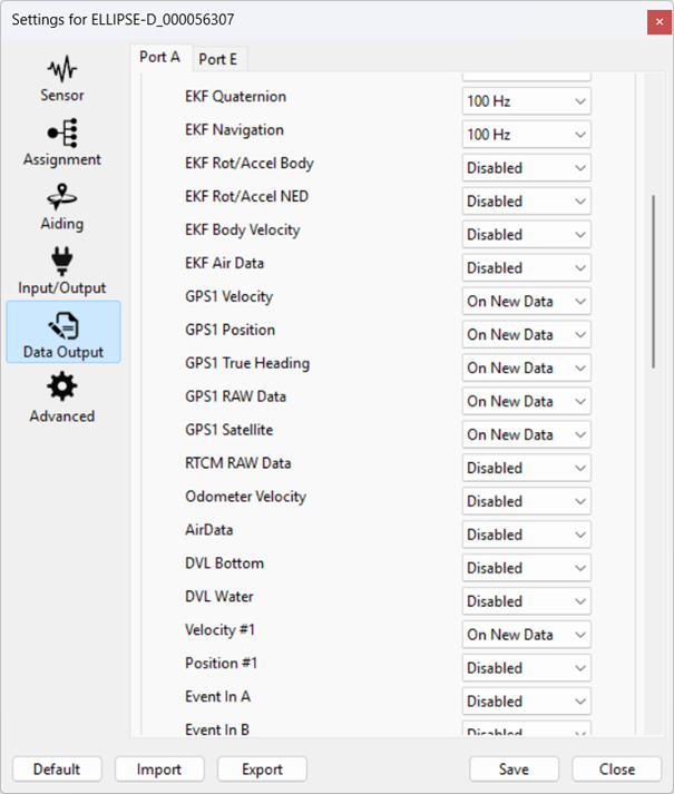
If you also want to output (or log) the generic velocity message, you can output it (or log it) by activating the dedicated message.
Operation
Data Check
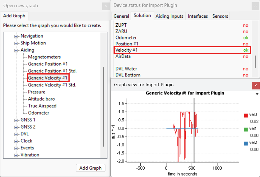
Once configured, it is recommended to check the availability and the order of magnitude of the data received. If Generic Velocity #1 message is activated on Port A as an output, you can plot it using sbgCenter.
While configuring the Generic Velocity input may initially seem "plug and play", integrating a new sensor usually requires the development of a dedicated error model. Note that these input values are used at face value within a basic error model, meaning inaccurate standard deviations may lead to navigation issues.
To achieve optimal performance, you can either attempt to tune your own standard deviations or have SBG Systems develop the error model with you. We highly recommend the second option. By letting us develop the error model, we can ensure the system benefits from better rejection thresholds, optimal standard deviation dilution, and overall improved robustness.
Because we do not expect most integrations to work perfectly out of the box without this tuning, we recommend the following workflow:
- Plug and check: Connect your sensor, configure the output, and verify data availability within the software.
- Acquire data: Record a representative dataset of your vehicle in standard operating conditions.
- Contact SBG Systems: Reach out to our technical support team with your acquired data so we can help you assess the quality the fusion.