Download PDF
Download page Integrate with PixHawk autopilots.
Integrate with PixHawk autopilots
Introduction
This article provides a practical guide for integrating a SBG Systems Ellipse INS with PixHawk-based autopilots. Whether you are using the PixHawk Mini or the Orange Cube, this document outlines the key steps for mechanical and electrical installation, PX4 and Ardupilot firmware configuration, and Ellipse setup. Designed to complement existing resources on GitHub documentation, this guide aims to help users achieve a robust and efficient integration using QGroundControl and MissionPlanner for monitoring and configuration. It ensures optimal performance by detailing all necessary parameters and best practices for a reliable navigation setup.
Mechanical installation
In this article we use an Ellipse-N single antenna that will rely on magnetometers to provide yaw angle. Using magnetometers is really delicate because they are sensitive to electromagnetic environment, so it's important to take that into account during the mechanical installation.
Here are some recommendations to take into account for the mechanical installation;
- It is really important that the INS is rigidly fixed to the autopilot and the antenna or antennas in case it's used as a INS.
- Keep the antenna(s) as far apart as possible from any eventual electromagnetic disturbance.
- Keep the antenna(s) as far as possible from propellers.
- Ensure proper mounting of the INS to prevent vibration (by considering a dampening solution or suspensions).
USB-C/USB-3
Please keep the antenna(s) as far as possible from any device that includes a USB-3/USB-C connector, as it's known to be a source of perturbation.
Electrical integration
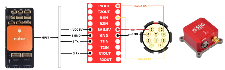
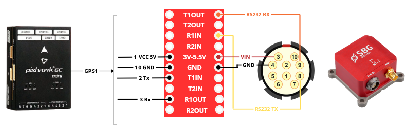
In these two examples we decided to connect the Ellipse to GPS1 port, but any other UART port can be used.
Orange cube
Requirements
- An Orange Cube.
- An Ellipse.
- An open wire fischer cable for Ellipse.
- A cable for GPS1 wiring.
- A TTL/RS232 converter. For the installation below, we use a MAX3232.
Wiring diagram
PixHawk-mini
Requirements
- A PixHawk-mini.
- An Ellipse.
- An open wire fischer cable for Ellipse.
- A cable for GPS1 wiring
- A TTL/RS232 converter. For the installation below, we use a MAX3232.
Wiring diagram
PX4 integration
PX4 firmware configuration
- Assign the correct serial port:
SENS_SBG_CFG=<Serial Port>from these different values;0: Disabled101: TELEM 1102: TELEM 2201: GPS 1202: GPS 2.
nsh> param set SENS_SBG_CFG 201
  SENS_SBG_CFG: curr: 0 -> new: 201
In our installation we used port GPS1, so it's important to disable GPS_1_CONFIG.
Set the baud rate: SBG_BAUDRATE
=<Desired Baudrate> from these values: 4800, 9600, 19200, 38400, 57600, 115200, 230400, 460800, 921600 bps.
nsh> param set SBG_BAUDRATE 921600
+ SBG_BAUDRATE: curr: 115200 -> new: 921600
- Set the priority for each accelerometer and gyroscope, by setting the Ellipse as the primary IMU
-1: Uninitialized0: Disabled1: Min25: Low50: Medium (Default)75: High100: Max.
param set CAL_ACC3_PRIO 75
+ CAL_ACC3_PRIO: curr: 0 -> new: 75
nsh> param set CAL_GYRO3_PRIO 75
+ CAL_GYRO3_PRIO: curr: 0 -> new: 75
External IMU will be always the one with the higher value. Orange Cube for example contains 3 IMUs, listed from 0.
Disable PX4’s internal EKF2 estimator EKF2_EN if using the SBG INS for navigation.
nsh> param set EKF2_EN 0
  EKF2_EN: curr: 1 -> new: 0
Configuration on QGC
Please note that on QGroundControl, it is possible to have some parameters missing, so the best thing to do is to search about it in the search field.
Ellipse configuration
The Ellipse with firmware V3, can be configured by different ways, with our own tools, via a GUI software (only available on Windows), or CLI. For more information please refer to this article Sensor configuration that will guide you on how to configure Ellipse using sbgCenter and RestAPI.
It is also possible to use it and configure it via our ROS2 driver.
It is important to configure some messages that the autopilot needs to fly correctly, such as:
- imu_short: it's the IMU raw data and it should be configured at least at 200hz.
- Published on these uORB topics: sensor_accel, sensor_gyro.
- ekf_mag: intensity of the electromagnetic field on x, y and z axis.
- Published on sensor_mag.
- Published on sensor_mag.
- ekf_quat: orientation expressed in quaternions.
- Published on vehicle_attitude uORB topic.
- ekf_nav: INS position and velocity, out of the EKF.
- Published on vehicle_local_position and vehicle_global_position.
- gps1_pos: GNSS position calculated by the receiver.
- Published on sensor_gps.
- gps1_vel: GNSS velocity calculated by the receiver.
- Published on sensor_gps.
- gps1_hdt: GNSS heading calculated between the primary antenna and the secondary (If you're using an Ellipse-D).
- Published on sensor_gps.
During the configuration make sure to proceed to a magnetic calibration. Please refer to our documentation on this topic to learn everything you need to know about this procedure.
Health monitoring
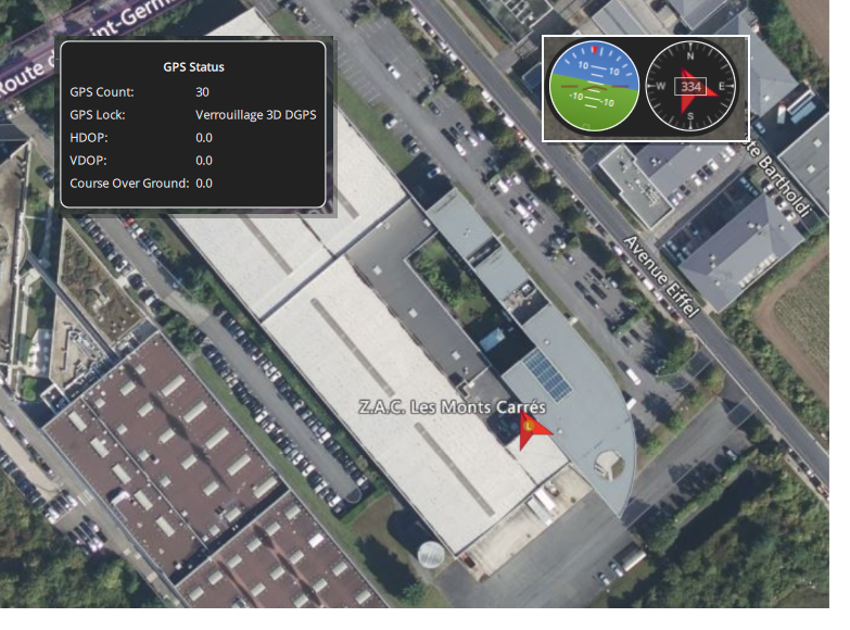
Once the installation and configuration is over, you can rely on various views proposed by QGroundControl.
Such as the number of satellites observed, horizontal view and 2D position.
And in MAVLink inspector you will find all the messages received.

If there is no data shown, you might want to check if the SBG driver is running or not.
nsh> sbgecom start
ERROR [sbgecom] Task already running
nsh> sbgecom status
Using port '/dev/ttyS2'
sbgecom: sample: 104794 events, 53847579us elapsed, 513.84us avg, min 11us max 4094us 516.086us rms
sbgecom: write: 12811 events, 175696us elapsed, 13.71us avg, min 9us max 122us 4.094us rms
sbgecom: errors: 0 events
ArduPilot integration
ArduPilot firmware configuration
To establish communication with the SBG Systems unit, set the following for the relevant serial port:
- Assign the correct serial port
SERIALx_PROTOCOL= 36 (AHRS) SERIALx_BAUD= matching SBG Systems sensor baudrate
The External AHRS-specific parameters may not be visible before the Serialx_Protocol parameter is configured. As such, either a Refresh Params or a reset of ArduPilot may be necessary to see the parameters.
ArduPilot can use a SBG Systems unit in two different ways:
As an External Sensor Set
ArduPilot takes the raw sensors from the INS (IMU, GNSS, magnetometer)
ArduPilot’s own EKF (EKF3) does the sensor fusion.
As an External AHRS (INS mode)
ArduPilot uses the SBG fused solution (position, velocity, attitude) directly
SBG’s INS becomes the main navigation source instead of ArduPilot’s internal EKF.
Use SBG as an external sensor set
AHRS_EKF_TYPE = 3 (ArduPilot’s EKF3)
EAHRS_TYPE = 8 (SBG Systems)
EAHRS_SENSORS bitmask to define which sensors will be used by ArduPilot's filters.
GPS/IMU/BARO/COMPASS are available
GPS1_TYPE = 21 (External AHRS)
If using a GNSS-enabled unit (Ellipse -N or -D)
Use as an External AHRS
AHRS_EKF_TYPE = 11 (External AHRS)
EAHRS_TYPE = 8 (SBG Systems)
Ellipse configuration
The Ellipse with firmware V3, can be configured by different ways, with our own tools, via a GUI software (only available on Windows), or CLI. For more information please refer to this article Sensor configuration that will guide you on how to configure Ellipse using sbgCenter and RestAPI.
It is also possible to use it and configure it via our ROS2 driver.
It is important to configure some messages that the autopilot needs to fly correctly, such as:
imu_short: it's the IMU raw data and it should be configured at least at 200hz.
mag: intensity of the electromagnetic field on x, y and z axis.
ekf_quat: orientation expressed in quaternions.
ekf_nav: INS position and velocity, out of the EKF.
gps1_pos: GNSS position calculated by the receiver.
gps1_vel: GNSS velocity calculated by the receiver.
gps1_hdt: GNSS heading calculated between the primary antenna and the secondary (If you're using an Ellipse-D).
air_data: barometric altitude and true airspeed.
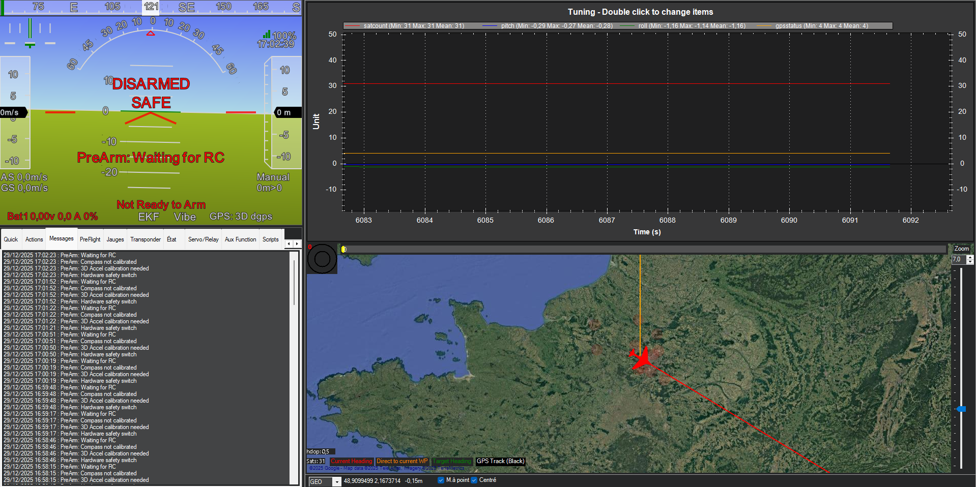
Health monitoring
Once the installation and configuration is over, you can rely on various views proposed by Qground Control or Mission Planner (Mission Planner below for example).
Such as the number of satellites observed, GNSS status or Roll/Pitch value.