Download PDF
Download page Magnetic calibration.
Magnetic calibration
Overview and background
This article describes how to calibrate Ellipse sensors, when they are strapped on an object that affects the local magnetic field.
Ellipse sensors are fully calibrated in factory. As for other sensors, magnetometers are fully temperature compensated. However, magnetic sensors are very sensitive to their close environment (mainly the objects on which they are strapped) : Some materials can generate magnetic fields that will be summed with Earth magnetic field, and some other can distort the existing magnetic field. These effects will be measured by magnetometers and will not be distinguished from the Earth magnetic field, and therefore error will occur in heading estimation. The amount of this error can be really significant, reaching dozens of degrees in many cases.
SBG Systems has carefully chosen materials that do not disturb magnetic field in the Ellipse hardware. So the unit itself should not disturb the magnetic field so much. Unfortunately, it is sometimes impossible to remove that kind of materials in customer system. There are two kinds of distortions, which are described below.
Hard Iron distortions
This kind of distortion is caused by magnets, or anything that acts as a magnet. It is very easy to magnetize objects like screws or nuts. Hard irons generate magnetic fields that are summed with the Earth magnetic field. Hard Iron effect shifts the magnetic field measured by magnetometers by a constant offset, whatever the device orientation is. Power supplies, which generate high current (several amps) and their associated wires, may also generate magnetic fields.
Soft Iron distortions
This kind of distortions are caused by ferromagnetic objects which are placed in the vicinity of the device. Iron, and some steels for example are ferromagnetic materials, but more generally, anything that sticks to a magnet is ferromagnetic. Ferromagnetic materials do not generate their own magnetic field. Instead of that, they react to existing magnetic field (in our case Earth magnetic field). By this way, Soft Irons distort the local magnetic field in a different way depending on the magnetic field direction. In addition to changing the magnetic field measurements, it also tends to rotate it compared to inertial reference frame. That rotation can be quite significant, reaching tens of degrees in some cases. This is why soft Irons are much more difficult to compensate for.
The most advanced calibration procedure available on the market
SBG Systems was the first company to introduce an easy to use hard & soft Iron calibration procedure in 2008 with the IG-500 series. Since then, Hard and soft Iron calibration became a standard in the inertial sensor industry.
Always looking for best quality, SBG Systems stays a step ahead by using a new compensation of magnetic coordinate frame alignment. When standard calibrations on market are subject to large and non-constant errors, SBG Systems guarantee a reliable, yet easy to perform calibration.
What can be compensated for and what cannot
It is critical to distinguish disturbances that can be calibrated from disturbances than can not be.
Distortions that come from materials which are fixed with respect to the device coordinate frame can be compensated for by the calibration procedure.
Distortions that are not fixed with the device, and move independently with respect to the device, or distortions that change over time, cannot be compensated for and must be limited as much as possible.
Distortions of the magnetic field act generally very locally, so in practice keeping the device far enough from the noise or time varying magnetic field might make the error negligible. Ideally, keep the device away from source of disturbances from at least 3 meters.
Kalman filter
Thanks to its internal Kalman filter, the Ellipse is able to cope for short term external distortions. Distortions that last up to a few minutes are handled without significant heading drift.
Procedure
The main goal of the procedure is to perform magnetic field measurements in many different orientations. This is done by rotating the device in different orientations to measure the magnetic field. SBG Systems exclusive algorithms are able to map the magnetic distortions in 3D and compensate for them. The more orientations will be passed through, the best the results will be.
If you cannot rotate the device freely in all possible orientations, the calibration algorithm can easily cope with it, and you will still get a good precision in orientations that were covered. However, a minimum of 9 significantly different orientations is required to perform the calibration.
Two types of calibration are provided depending on the degree of freedom of the device:
Important Note
In order to get good results, it is important to keep away from at least 3 meters all external sources of magnetic disturbances. Keep in mind that a building structure generally contains steel and other sources of interference, as well as computers, chairs, desks, etc.
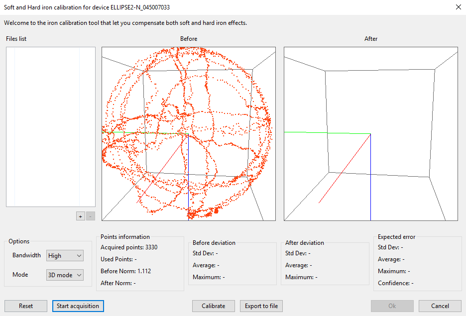
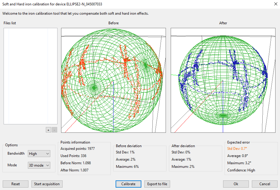
3D Calibration
3D calibration procedure is the standard procedure and should be preferred as it will provide the best performance in most applications. When user starts it, the device has to be rotated through the maximum amount of different orientations. User has simply to rotate the device regularly at a relatively slow rate (< 250°/s rotations are acceptable). Too fast movements may weaken results.
Ideally, the points should draw a complete ellipsoid shape. User has to try to cover a maximum of this ellipsoid shape to get the best results. After calibration, the magnetic field norm should equal 1.0 in all orientations. In this case, all points after calibration should be placed on a unit 3D sphere.
The 3D calibration requires sensor position (Latitude, Longitude, Altitude) and date information in order to work properly. It can be provided by “initial parameters” on an Ellipse-A product, or/and when the system has entered in navigation mode for Ellipse E and N models.
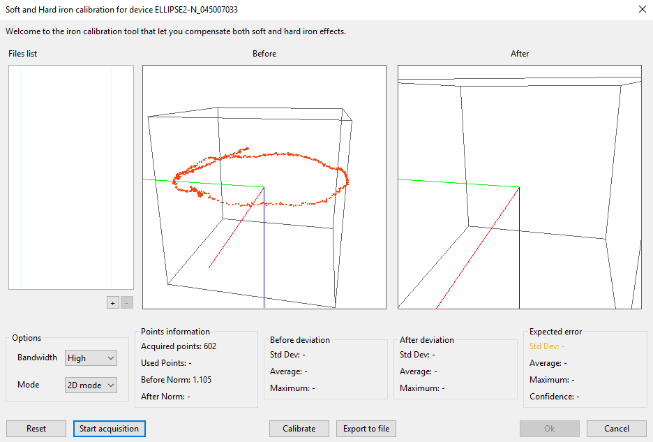
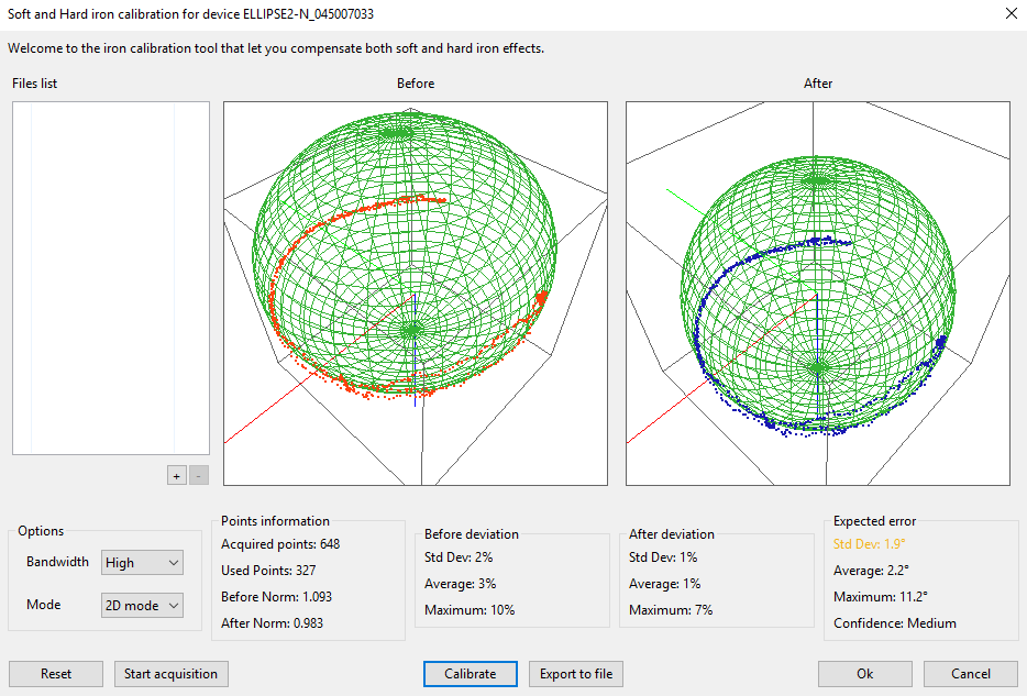
2D Calibration
Sometimes, it is not possible to move the device in 3D. A 2D calibration is intended for these cases. The procedure is just to rotate the device through a horizontal circle. It is possible to cover less than a full circle, but best results are achieved with a full 360° coverage. Before the calibration is performed, the magnetometers readings should form a 2D ellipse. After calibration, the magnetic field norm should equal 1.0 in all orientations. In the 2D case, all possible magnetic fields should be placed on a unit circle.
The 2D calibration algorithm is specifically designed to make the best use of all available data, even with a very limited motion. However, due to physical and mathematical constraints, it is not possible to fully realign magnetic and inertial coordinate frames in that calibration mode. This can lead to a residual offset on the heading measurements that depends on the magnitude of disturbances to correct.
There is no way to estimate this offset but you can read it by placing the device to a known heading.
The 2D calibration requires sensor position (Latitude, Longitude, Altitude) and date information in order to work properly. It can be provided by “initial parameters” on an Ellipse-A product, or/and when the system has entered in navigation mode for Ellipse E and N models.
Calibration methods
SBG Systems now supports two calibration methods that offer the same performance level. The choice of the method to use depends on the user integration constraints.
- sbgCenter method which is the easiest way to proceed and should suit to most applications. It can use either real time data, or previously recorded data. This requires a computer connected to the sensor, but it gives a nice and powerful real-time feedback.
- On-board calibration method, that provides similar performance as the above one, but that do not require any special piece of hardware to be executed. The Ellipse does it by itself when it receives corresponding commands!
sbgCenter method
This method is advised if a computer can be connected to the device. It is very flexible and allows real time calibration, as well as calibration with log files.
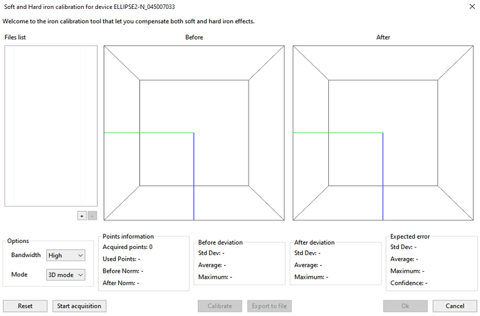
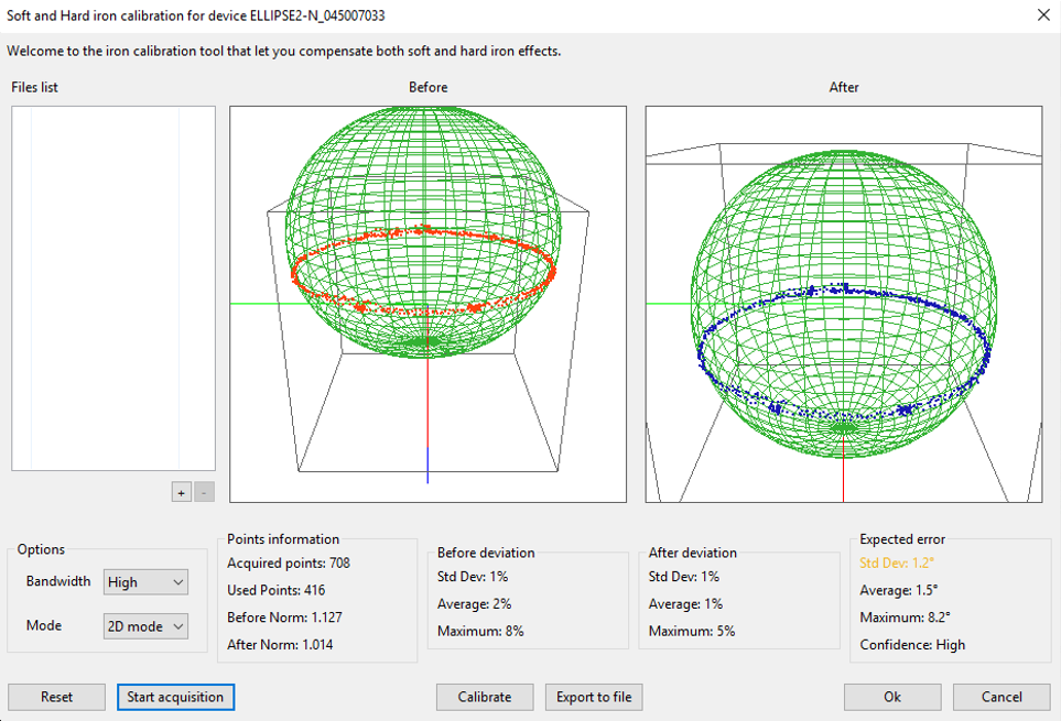
Presentation of the calibration window
On the left of the window, a file list is available to include log files to reprocess or that has been previously recorded. Multiple files can be used for a single calibration.
Then, two 3D plots are displayed:
- The first, “Before” shows all points in 3D as they are measured by magnetometers before any hard/soft iron calibration. This display is updated in real time.
- The second one, “After” will show the same points, transformed by the calibration algorithm. This display will only be updated once the Calibrate button is pressed.
These 3D plots can be easily rotated with the mouse, and you can also zoom in/out with the mouse wheel. When you rotate a plot, the second one will also rotate so that the field of view remains the same in the two displays.
On the bottom, several buttons allow to:
- Reset calibration data
- Start/ Stop Real time acquisition
- Calibrate acquired data
- Save acquired data for future use
- Finish or cancel calibration
A few options will allow user to tune calibration behavior. These options can be used before or after the acquisition has been performed, so it's possible to try new settings to see if the calibration is better performed in 2D or in 3D.
- Bandwidth, set to “High” by default, can be reduced to improve calibration robustness against noisy magnetic field environments. In case of selecting “Normal” or “Low” bandwidth, it's then recommended to move slowly the sensor during calibration (rotations < 100°/s). If observations are really noisy, then this threshold will more likely reject the calibration when set to High than when set to Normal or Low.
- Mode can be set to 3D or 2D. 3D is the default one and should be used as long as it's possible to provide sufficient motion. In fact, 2D calibration is a locally true correction which means that for large roll and pitch angles and/or non negligible latitude changes, magnetic north would be rejected.
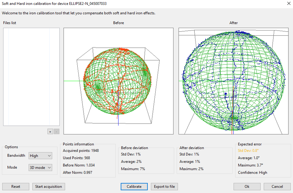
Finally a few boxes will inform user about the calibration procedure, its results, and some quality hints:
- Points information: The number of collected points is displayed. The more points will be collected, the better the calibration will be. The length of the current magnetic field (“After Norm”) is displayed once the calibrate button is pressed. This length should always equal one in all orientation with a good calibration.
- Before deviation: This information is updated each time the calibrate button is pressed. It informs about the distortion of the local magnetic field before calibration. The average deviation is representative of the magnetic field. STD Dev defines the noise observed, and the maximum deviation informs about how noisy the environment is.
- After deviation: This is the deviation of the magnetic field, when the full calibration algorithm is applied. The average deviation is the most representative information. STD Dev defines the noise observed, and max deviation represents the worse case of all measurements performed during calibration.
- Expected error: Finally, this box shows in term of degrees the expected magnetic heading error after the full calibration. The STD error is the most representative information, and it comes with a color code (Dark green optimal, Green is good, Orange is acceptable, Red is bad), which represents the confidence in the calibration results. Max error represents the worse case of all measurements performed during calibration. If the max error is high, it may come from a disturbed magnetic field during calibration.
Real Time Procedure
Before launching the calibration procedure, it is recommended to put the device in a place free of external magnetic fields (more than 3 meters of any source of distortion).
Step 1: Start/Reset the procedure
Once you have started the Soft and Hard Iron Calibration Tool, the following window appears. When the device is ready for calibration, you can click on the Start Acquisition button.
Step 2: Rotate the device
Rotate the device ideally around each axis pointing downward and then upward for a 3D calibration. For a 2D calibration, just make sure to rotate roughly in a plane (avoid too much roll/pitch motions). Rotate the device slowly to get the best results. We recommend at least 8s to to complete a full 360° rotation around one axis.
Step 3: Press the “Calibrate” button
If the calibration tool detects some issue during calibration, a pop-up window will appear to tell you what is wrong. Possible errors might be having not enough motion observed during calibration, or alignment issues that come from a too fast motion or too noisy magnetic field.
Step 4: Press OK to finish procedure.
The calibration data will be sent to the device and saved into internal Flash memory.
On-board calibration
The on-board calibration method shares the same principle of operation as the sbgCenter one. So we suggest you to first make use of the sbgCenter method to get familiar with the concepts involved in the magnetic calibration before using the on-board method.
On-board and sbgCenter methods will provide similar performance. The on-board calibration has just a smaller memory than a standard PC, so it's not able to store more than 1000 calibration points. Please note that this will not affect performance as an intelligent system only stores relevant points in the internal memory.
The on-board calibration is using different low level commands to achieve the full procedure, and we will basically run the same steps as sbgCenter method.
All the attributes mentioned above in the sbgCenter method and resulting from the calibration process will be available with the On-board calibration method, except the “After Norm” value. Quality and confidence indicators will be provided instead:
Quality indicator
- 0 Optimal: Magnetic field is very coherent with inertial motion after calibration
1 Good: Small magnetic field deviations from inertial motion have been detected. The magnetic calibration should still provide accurate heading.
2 Poor: Large magnetic field deviations from inertial motion have been detected.
- 3 Invalid: No valid calibration has been computed. Magnetic calibration have failed or partially failed (Refer to error pop-up).
Confidence indicator
- 0 High: Reported quality indicator can be trusted.
- 1 Medium: Few remarkable magnetic field points have been used.
- 2 Low: The data set used to compute the magnetic calibration was not meaningful.
Calibration should be considered applicable if Quality indicator is 0 OR 1, AND confidence indicator is 0.
Procedure
Initiate the calibration
The command SBG_ECOM_CMD_START_MAG_CALIB is sent to the Ellipse to start magnetic calibration. At this point, user must define some calibration parameters:
- Bandwidth must be selected (high, medium, or low bandwidth). High is the default one; other options are useful to cope with noisy magnetic fields.
- 2D or 3D calibration mode.
Compute calibration parameters
Using the command SBG_ECOM_CMD_COMPUTE_MAG_CALIB, the Ellipse will compute all calibration parameters, and will return the calibration result, with advanced quality indicators, and indication about how to solve any calibration issues.
Store calibration parameters into the Ellipse internal memory
Once proper calibration parameters have been returned by the Ellipse, the user can decide to apply it. In order to do so, the command SBG_ECOM_CMD_SET_MAG_CALIB must be sent with returned correction vector and matrix as parameters.
Finally, the new configuration must be sent to flash memory for use at the next boot, using SBG_ECOM_CMD_SETTINGS_ACTION command.
Advices and limitations
Cover a maximum of different orientations
Best results will always be given when a wide range of orientations is covered during calibration. In theory only a few orientations would be necessary to map the whole magnetic field. But due to noise measurements, external magnetic fields and other effects, it is always better to collect the maximum amount of data to get good results.
Limited degrees of freedom
If the device cannot be rotated freely in all orientations, the algorithm will still be accurate, but only in orientations that were covered during calibration procedure.
Keep away from any external sources of distortion
The magnetometers and the calibration algorithm cannot distinguish between distortions caused by external magnetic fields and distortions caused by the object on which the device is strapped. Those external distortions can be generated by the building structure, or Iron desks, computers etc.
It is therefore very important to move away the device from ferromagnetic objects within about 3 meters.
This recommendation becomes even more important if the calibration is performed within a limited set of orientations.
Specific applications
The Magnetic calibration for airborne applications page details how to perform the mandatory calibration process on airborne applications.
The Magnetic calibration for marine applications page details how to perform the mandatory calibration process on marine applications.