Download PDF
Download page Sensor configuration.
Sensor configuration
Doc for Ellipse firmware ≥ 3.0
You are currently viewing the documentation for an Ellipse running firmware version ≥ 3.0. If your Ellipse is operating on firmware version 2.x or earlier, please use the version picker in the top-right corner of the page to select the appropriate version.
This guide is designed to help you perform the initial configuration of the Ellipse using the sbgCenter and sbgInsRestApi. These settings are common to all applications.
Using sbgCenter
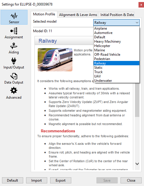
Motion profile selection
This panel allows you to setup the motion profile for your application. Select here the profile that best fits your application to ensure optimal behavior.
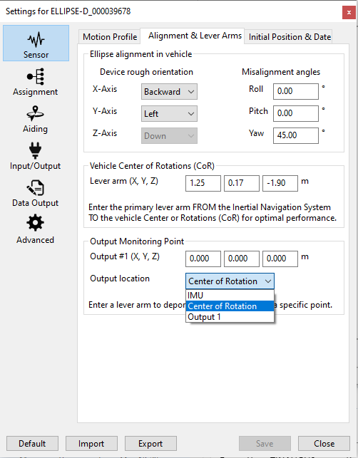
Mechanical setup
The vehicle frame is defined with +X pointing forward, +Y to the right, and +Z pointing downward.
This panel allows you to setup the mechanical setup of your INS within the vehicle. You need to configure the following parameters:
- Rough alignement: which defines the overall orientation of the INS in the vehicle
- Fine misalignment: to address any residual misalignment between the two along three axes
- Center of Rotation lever arm: from IMU to CoR in vehicle frame
- Output monitoring point lever arm: distance from the IMU to a point of your choice where all outputs will be referenced (only used if you set Output Location to Output 1)
- Output location: the point to which all the outputs will be referenced
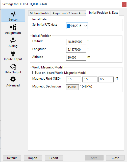
Magnetometer-related parameters: initial position and date
This section can be ignored if the magnetometers are not used in your application.
In order to correct for magnetic deviation when using magnetometers, two options are available:
- Using the embedded WMM: for that the initial position and date are required
- Using your own magnetic reference: in that case, you should configure the local magnetic field along the three axis
Using REST API
Before proceeding with the following steps, you need to identify the Ellipse's COM port and baud rate. This can be easily done using SBG Center.
Next, download sbgECom API and open a Command Prompt in the sbgECom API directory and you are ready to configure your Ellipse.
Motion profile configuration
COM Port to use
The following examples use the serial port COM12 and a baudrate of 921600. When running these commands on a PC, make sure you identify the right COM port and baudrate using sbgCenter.
To get the Ellipse current motion profile:
sbgEComApi.exe -s COM12 -r 921600 /api/v1/settings/insFilter/motionProfile -g
The Ellipse answer is for example:
{"automotive"}To change the current motion profile, refer to the motion profile identifier in the sbgInsRestApi documentation. For instance, below an example to apply "railway" motion profile.
sbgEComApi.exe -s COM12 -r 921600 /api/v1/settings/insFilter/motionProfile -p -b \"railway\"
The Ellipse answer is:
{"title":"request successful","needReboot":true}As indicated in the response, you will need to reboot the Ellipse for the configuration to be effective.
Mechanical setup
To set up the installation of your Ellipse within the vehicle, you need to configure the following parameters:
- Rough alignement: which defines the overall orientation of the INS in the vehicle
- Fine misalignment: to address any residual misalignment between the two along three axes
- Center of rotation lever arm : from IMU to COG in vehicle frame
- Output monitoring point lever arm: distance from the IMU to a point of your choice where all outputs will be referenced
To set the rough orientation of the INS:
sbgEComApi.exe -s COM12 -r 921600 /api/v1/settings/mechanicalSetup/alignment/rough -p -b [\"backward\",\"left\"]
To set the fine misalignment of the INS:
sbgEComApi.exe -s COM12 -r 921600 /api/v1/settings/mechanicalSetup/alignment/fine -p -b [0,0,45]
To configure the CoR lever arm:
sbgEComApi.exe -s COM12 -r 921600 /api/v1/settings/mechanicalSetup/leverArms/cog -p -b [1.25,0.17,-1.9]
sbgEComApi.exe -s COM12 -r 921600 /api/v1/settings/mechanicalSetup/leverArms/output1 -p -b [0,0,0]
Magnetometer-related parameters
In order to correct for magnetic deviation when using magnetometers, two options are available:
- Using the embedded WMM: for that the initial position and date are required
- Using your own magnetic reference: in that case, you should configure the local magnetic field along the three axis
For the first option, you should:
sbgEComApi.exe -s COM12 -r 921600 /api/v1/settings/localParam/useOnBoardWMM -p -b true
sbgEComApi.exe -s COM12 -r 921600 /api/v1/settings/localParam/latitude -p -b 48.8688
sbgEComApi.exe -s COM12 -r 921600 /api/v1/settings/localParam/longitude -p -b 2.1577
sbgEComApi.exe -s COM12 -r 921600 /api/v1/settings/localParam/height -p -b 30
sbgEComApi.exe -s COM12 -r 921600 /api/v1/settings/localParam/date -p -b \"2024-01-01\"
For the second option you should:
sbgEComApi.exe -s COM12 -r 921600 /api/v1/settings/localParam/useOnBoardWMM -p -b false
sbgEComApi.exe -s COM12 -r 921600 /api/v1/settings/localParam/magneticRef -p -b [0.5,0.5,0.5]
Complete documentation of the sbgInsRestAPI
The above examples highlight some of the commands available.
The full up-to-date documentation, of the API can be found at the following link: Configuration API (sbgInsRestApi)