Download PDF
Download page DVL - Doppler Velocity Log Integration.
DVL - Doppler Velocity Log Integration
This operating handbook aims to guide users for DVL sensor installation and configuration in marine environments. This guide is intended for the integration of any DVL systems outputting Teledyne RDI PD0, PD6, Wayfinder message or Nortek DF21/DF22, Nucleus messages.
Use this document in complement of the Operating Handbook “Use in Marine Applications”.
Mechanical installation
DVL frame update
Since the release of the HPI firmware 5.2.1203, The SBG products now support DVLs with a NED or ENU frame convention.
The DVL must be rigidly fixed to the vessel structure.
It is recommended to align the DVL forward mark toward the vessel bow.
For a DVL with NED frame convention
The settings are straight forward, you just need to report the misalignment angles from vehicle reference frame
The axis alignement is X-Forward, Y-Right (Z-Down) and alignment angle to enter in the inertial system configuration is Roll=0°, Pitch=0°, Yaw=0°.
For a DVL with ENU frame convention
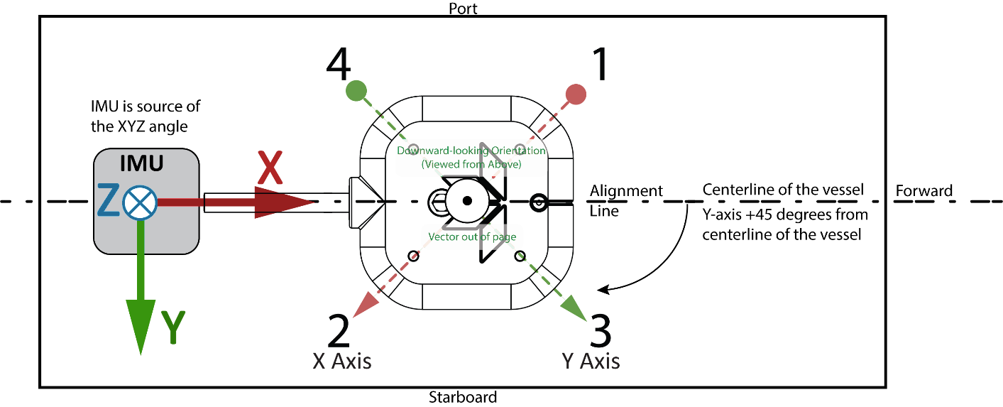
The axis alignement is X-Backward, Y-Right (Z-UP) and the alignment angle to enter in the inertial system configuration is Roll=0°, Pitch=0°, Yaw=-45°.
Electrical connections
The typical DVL electrical integration takes care of two main aspects:
- The DVL data output
- Synchronization between DVL and INS
Data output connection
Regarding the data output, a simple serial connection is generally used, by connecting the DVL serial port to one of the SBG INS available serial ports (eg. PORT A Rx), either in RS-232 or in RS-422.
Synchronization between DVL and SBG INS
DVL Master
In this mode of operation, the DVL runs on its own and can send a synchronization pulse to the SBG INS whenever a new velocity measurement is available.
The measurement rate might be not constant depending on water conditions.
To operate in this mode, the DVL synchronization output must be connected to one of the available SBG INS SYNC IN pins.
DVL Slave
In this mode of operation, the SBG INS generates a regular pulse signal to trigger each measurements of the DVL.
The measurement rate can be constant in this mode, driven by the SBG INS SYNC OUT rate.
However care must be taken in setting up the SYNC OUT Rate to mach the minimum DVL's timing requirement, based on DVL type, configuration, and maximum depth during the mission.
In other words, the DVL must be able to send a ultrasonic pulse, wait for the echo and process the data before the next trigger shall occur.
Setting the right rate
SBG Systems recommends you to contact your DVL's manufacturer to know what allowable SYNC OUT rates can be used depending on your system configuration and water environment.
As a rule of thumb, an update rate between 1Hz and 10Hz is feasible in shallow water conditions.
Software configuration
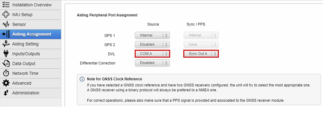
Aiding Assignment
Select the DVL on the input port of your choice (COM or ETH port) and the synchronization source used to time stamp DVL data.
Aiding Settings
In Aiding tab we select the frames model, rough orientation, fine misalignment and lever arms, then finally the rejection of the DVL. (Auto rejection is recommended)
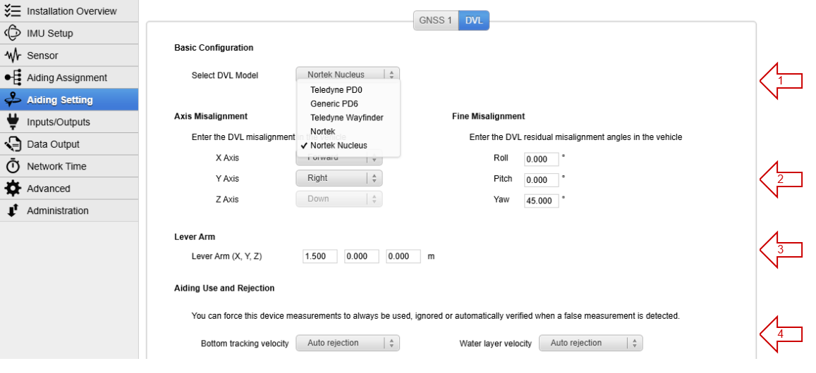
Select the communication protocol : Teledyne for PD0 (binary) , Generic PD6 (ASCII) , Teledyne Wayfinder (binary), Nortek (DF21/DF22), or Nortek Nucleus message format.
- Set the rough orientation axis and fine misalignment angles of the DVL in the vehicle reference frame. (The orientation should be left to zero in DVL software to be entered here).
- Select the lever arm from the IMU to the DVL position in the vehicle reference frame (with X forward, Y to the right, and Z down).
The Aiding rejection Automatic is advised for both Bottom and Water, so the Kalman filter determines the confidence of this parameter by itself.
PD6 requirements
When using the PD6 format, the following PD6 frames are required: SA, TS, WI, WD, BI, BD.
Input / Output
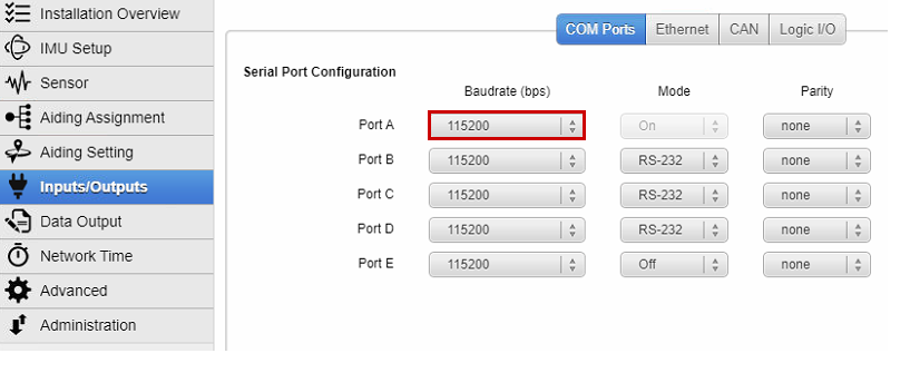
COM Ports
Configure the baudrate of the serial port you chose in the Aiding Assignment section. Also configure the mode (RS-232 or RS-422) for the relevant serial port.
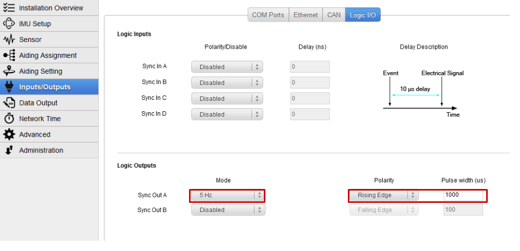
Logic I/O
Configure the synchronization input or output, making sure it matches the DVL polarity and timing requirements. Our example shows that we use the DVL in a slave mode and an update rate of 5Hz.
Data Output
For data check, make sure you output the DVL Bottom Track and DVL Water Layer on “New Data” in the ETH 0 interface:
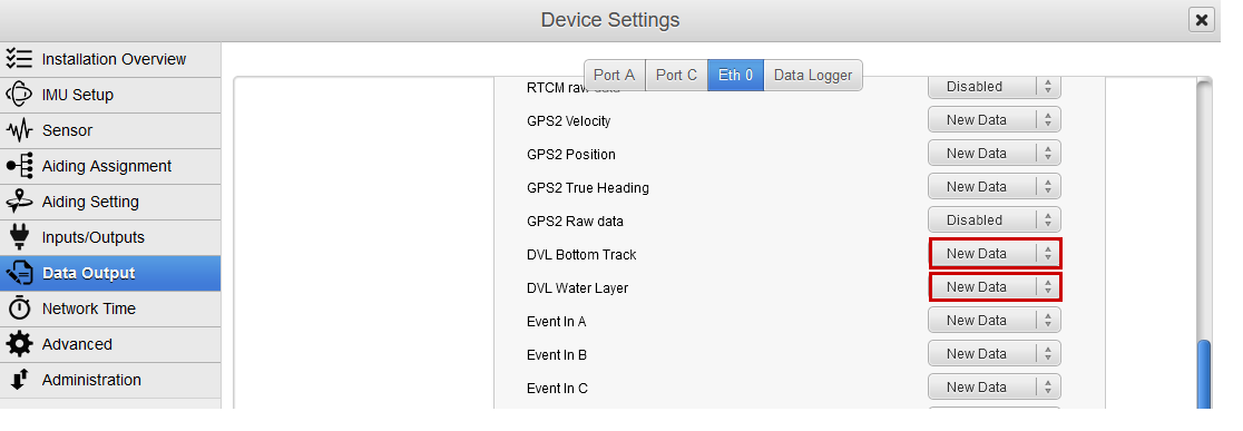
This is not mandatory for DVL use, but will allow to check the data received from the DVL in the sbgCenter.
It is also strongly recommended to use the “Support” output preset in the Data Logger section, and let it activated for the test run. This way logs can be replayed and data checked later in the sbgCenter or in a text file export.
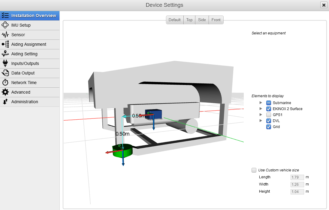
Installation Overview
The whole configuration can easily be checked in the Setup Overview section. It features a 3D display that can be modified by simply clicking on an item, then changing the orientation or lever arm values. Any change will be directly visible.
Operation
Data check
You can also check the DVL data directly in the sbgCenter: Please note the velocities will be directly the ones from the DVL, so no orientation compensation will be applied (it is only applied internally by the Kalman filter).
In the following example, we got a velocity on the X and Y axes because the DVL was installed with a 45° angle.
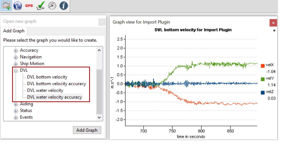
This requires that you output the DVL Bottom Track and DVL Water Layer in the Data Output section.
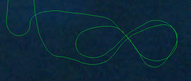
DVL Calibration
At each start, your INS will automatically calibrate and adjust your DVL installation parameters, as well as DVL's scale factor. This process can be performed in the following conditions:
- Good GNSS reception: To Initialize and warm-up the INS and be used as a reference for DVL alignment and gain estimations.
- Dynamic motion : DVL calibration parameters need some dynamic maneuvers to be "observed" and refined by the Kalman filter.
A typical alignment pattern is shown in the next picture: