Download PDF
Download page Odometer Integration.
Odometer Integration
This operating handbook aims to guide users for Odometer sensor installation and configuration in land applications. This guide is intended for the integration of Odometer systems outputting TTL pulses.
Use this document in complement of the Operating Handbook “Use in Land Applications”.
All our INS models provide an odometer input which can greatly improve performance in challenging environments such as urban canyons.
The odometer provides a reliable velocity information even during GNSS outages. This increases significantly the dead reckoning accuracy.
Our products support:
- Quadrature output or compatible odometers with forward and reverse directions.
- CAN vehicle velocity messages (fully configurable) for setup with direct interface with vehicle’s ODBII connector when using the Ellipse series.
Odometer integration is made really simple as the EKF will finely adjust odometer's gain and will correct residual errors in the odometer alignment and lever arm.
Mechanical Installation
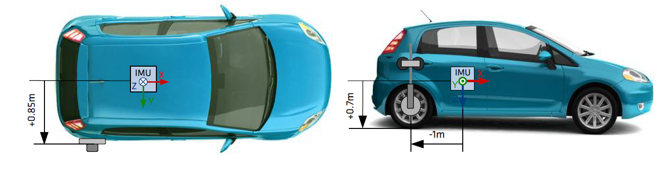
The Odometer has to be placed on a non steering wheel (rear wheel in most applications).
The Odometer lever arm has to be measured. It is the signed distance, expressed in the vehicle coordinate frame, FROM the IMU TO the point of contact between the ground and the tire where the Odometer is installed. It has to be measured with 5cm accuracy.
Electrical installation
SBG Systems INS devices support several DMI (Distance Measurement Instrument) devices and conventions. You can connect simple pulse odometer to more complex quadrature wheel encoders that provide both a velocity and a direction of travel.
For more information, check out the dedicated page.
Wiring the odometer input
Each SBG products include pins that can alternatively be used as odometry input. Which port can be used is specified in the individual documentation of each product.
Make sure you respect the following:
- Your Odometer channel A signal is connected to the pin marked as "Odometer A" on the documentation.
- Your Odometer channel B signal is connected to the pin marked as "Odometer B" on the documentation.
- The GND pin of the odometer is tied to the GND pin of the sensor.
Single Channel Odometer wiring
In case of single channel odometer, please tie the second odometer input (Odometer B) pin to GND to force the system in normal direction.
Software configuration
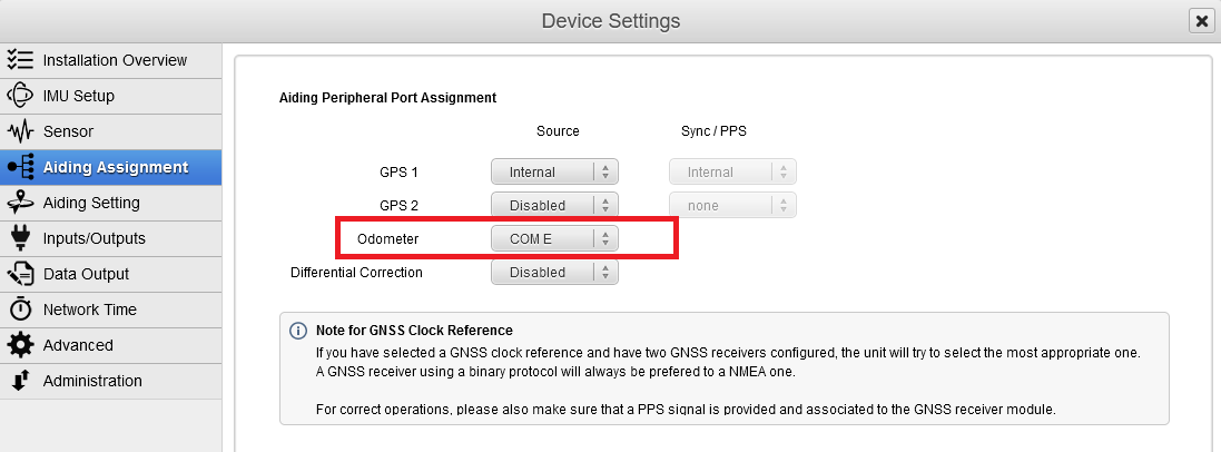
Aiding Assignment
Select the Odometer on the right input port.
Aiding Settings
If you are using an odometer and activated it in Aiding Assignments, you will see a thumbnail called “odometer” in the Aiding Settings panel.
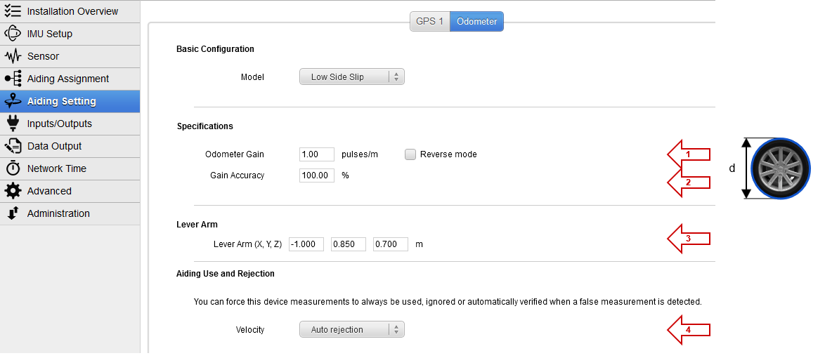
- Define here the initial Odometer Gain expressed in pulses per meter.
- Gain Accuracy defines how precise is entered the gain. The default value of 100% will let the internal Kalman filter refine the gain automatically and is recommended in most applications.
- Depending on your hardware configuration, the reverse mode can be used to reverse the velocity value in order to fit with an actual velocity direction.
- Set up here the Odometer lever arm depending on its position from the IMU to the wheel point of contact on the road, expressed in the vehicle reference frame (X forward, Y to the right, and Z down). A 5cm accuracy or less is required.
- The Aiding rejection Automatic is advised so the Kalman filter determines the confidence of this parameter by itself.
Converting pulses per revolution into pulses per meter
Your odometer might specify a number of pulses per revolution. To convert that value into the expected gain in pulse / m, You will typically have odometer specified in number of pulses per revolution, so you need to convert it into pulses/m as follow:

With P being the number of pulses per revolutions, d being the wheel Perimeter.
Example with a 128 pulses/revolution odometer on a 40 cm diameter wheel:
Gain = 128 / (π x 0.4) = 101.86 pulses/m
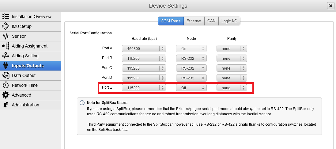
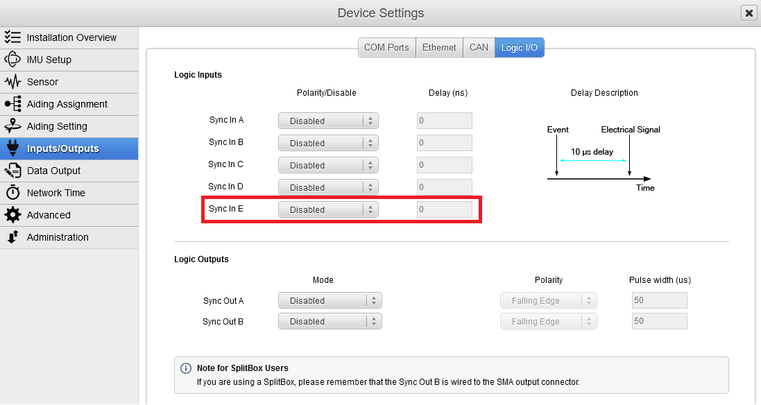
Input / Output
Configure Port E to Off mode. In the same way, set Sync In E to Disabled to avoid disturbing odometer operation.
Data Output
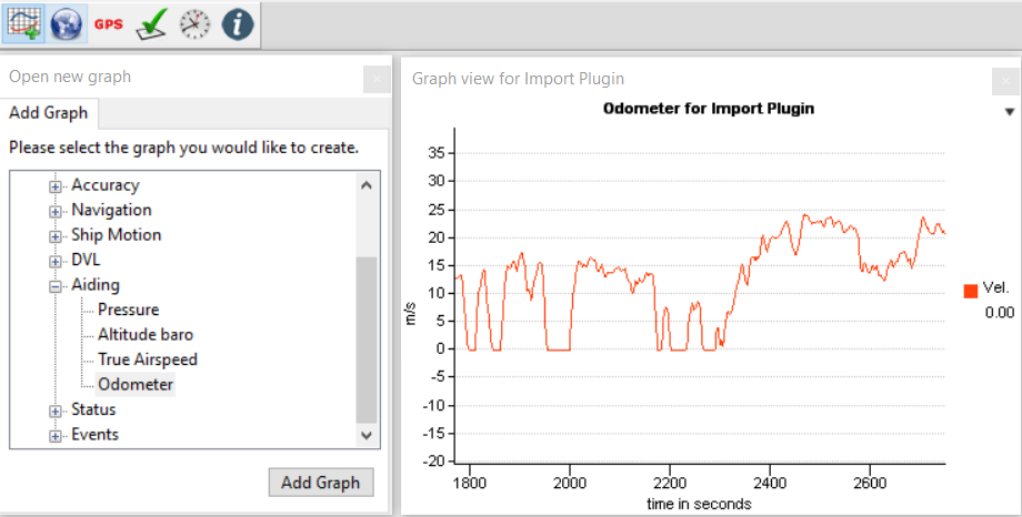
For data check, make sure you output the Odometer on “New Data” :
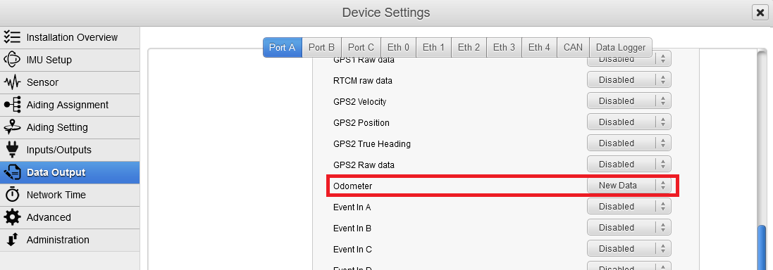
This is not mandatory for Odometer use, but will allow to check the data received from the Odometer in the sbgCenter.
This is also strongly recommended to use the “Support” output preset in the Data Logger section, and let it activated for the test run. This way logs can be replayed and data checked later in the sbgCenter or in a text file export.
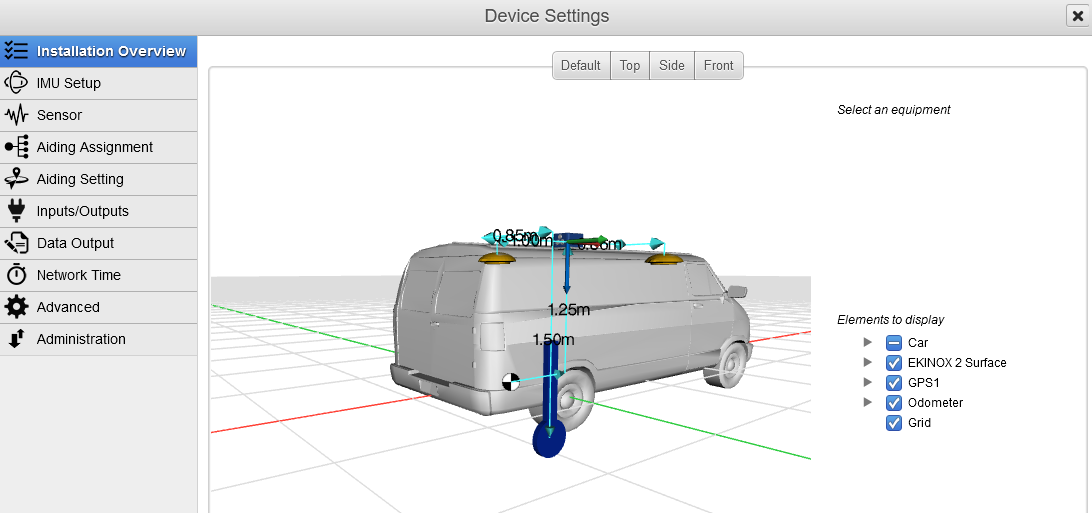
Installation checking
The whole configuration can easily be checked in the Setup Overview section. It features a 3D display that can be modified by simply clicking on an item, then changing the orientation or lever arm values. Any change will be directly visible.
 Data checking
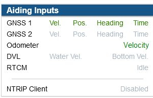
You can check your installation in the status information panel. Odometer velocity should be marked as valid.
You can also check the Odometer data directly in the sbgCenter, and compare it to GNSS velocity to track for any gain configuration error.