Download PDF
Download page External Septentrio GNSS integration.
External Septentrio GNSS integration
This brief document guides you in the process of connecting an external Septentrio GNSS receiver to your SBG High Performance product.
Use this document in complement of the “Operations” Operating Handbooks.
Step 1 : GNSS and sensor connections
Two physical communication layers can be used for feeding the aiding data frames to the INS : serial communications (recommanded) or Ethernet (not in the scope of that document).
In both case, connect GNSS PPS signal to an available Sync Input.
In case of serial communications, connect GNSS Tx signal(s) to one of the available serial ports Rx pin.
Step 2 : GNSS module configuration
Septentrio configuration can be performed using RxControl, or the embedded web interface.
Basic operation
Configure the following outputs and output rates on your GNSS receiver:
PVTGeodetic @ 5 Hz
PosCovGeodetic @ 5 Hz
VelCovGeodetic @ 5 Hz
AttEuler @ 5 Hz (if applicable, on dual antenna systems)
AttCovEuler @ 5 Hz (if applicable, on dual antenna systems)
ReceiverTime @ 1Hz
AuxAntPosition @ 1Hz
xPPSOffset @ 1Hz
PPS signal
For proper operation, a PPS signal must be provided at 1 Hz. Please configure the Septentrio receiver to output a PPS signal at 1 Hz on a rising edge (Low2High).
Septentrio PPS signal strength is usually weak (3V pulse). If the PPS cable is too long or split, this signal may require pre‑amplification using third party hardware to work properly.
Adding post-processing capability
The output set “PostProcess” must be enabled at 1Hz as well for post-processing operation, It contains the following output:
MeasEpoch, MeasExtra @ 1Hz
GEORawL1 @ 1Hz
GPSNav, GPSIon, GPSUtc @ 1Hz
GLONav, GLOTime @ 1Hz
GALNav, GALIon, GALUtc, GALGstGps, GALSARRLM @1 Hz
BDSNav @ 1Hz
QZSNav @ 1Hz
DiffCorrIn @ 1Hz
ReceiverSetup @ 1Hz
Commands @ 1Hz
Other GNSS Configuration
Receiver dynamics should be set to:
Acceleration / Jerk: High
Motion: Unlimited
Smoothing options must be disabled.
Step 3 : Sensor configuration
In order to configure the Sensor, you need to connect to the Web interface and open the configuration window. Simply follow those instructions:
Set aiding assignment
In this window, you just indicate where you connected your GNSS receiver.
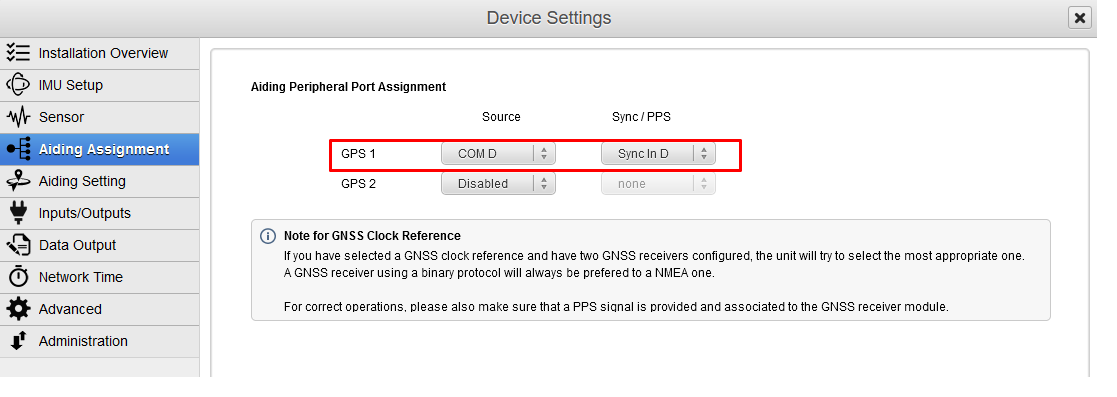
Both communication port and Sync In pin must be set.
If you have two connected GNSS receivers, only the primary GNSS receiver should provide a PPS source to accurately time stamp the data.
Set correct baudrate and mode for serial port
In our example we configured the GNSS to be connected on PORT D in RS‑232 mode using a baudrate of 460800 bauds.
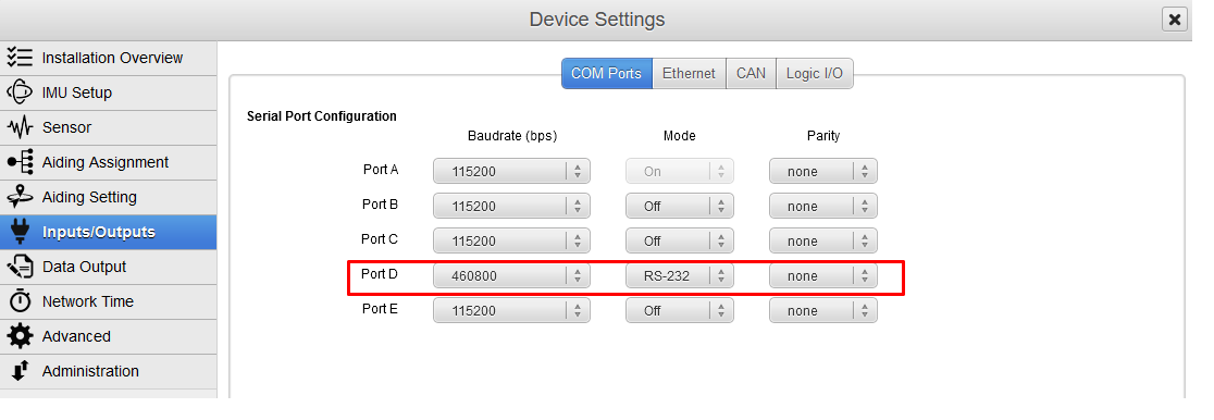
Post Processing messages contain a lot of packets, sufficient baudrate speed should be then selected. We recommend a speed of 460800 bauds in that case.
Set logic input configuration for PPS signal
In order to use correctly PPS signal information, you must enable the corresponding logic input. Here we configured PPS on Sync In D.
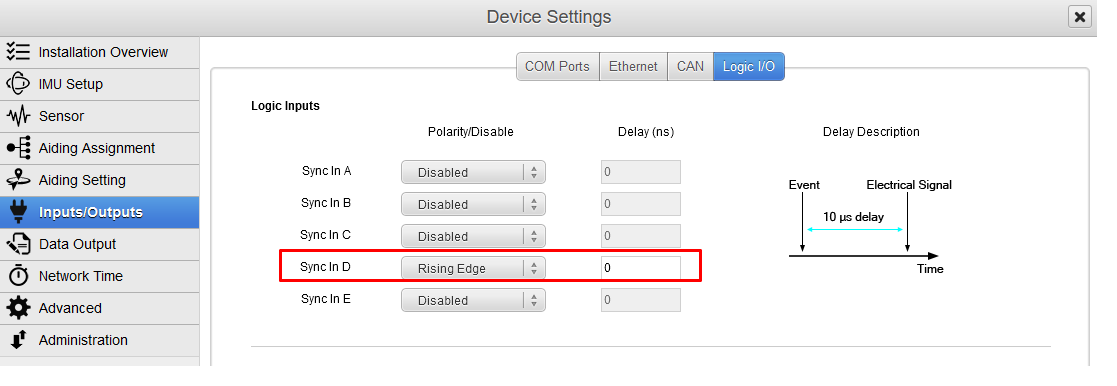
Polarity should be set accordingly with the actual PPS signal which is provided by your GNSS receiver.
Set correct GNSS model and configuration
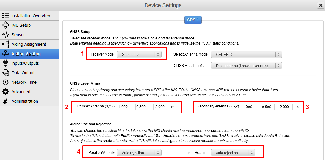
GNSS model should be set to Septentrio.
GNSS Primary lever arm has to be entered within a 1 cm accuracy FROM the IMU reference point, TO the antenna reference point (ARP), in the vehicle frame.
In Dual Antenna (known lever arm) mode, offset for the secondary antenna (providing heading) must also be entered, FROM the IMU reference point, TO each antenna reference point. It is also possible to select Dual Antenna (auto lever arm) if a calibration is planned for the antennas lever arms.
Finally, each available measurement (position/velocity and true heading if available) should be configured to be used or not. Auto rejection mode is recommended.
In order to increase the precision of the measurements it is recommended to select the actual Antenna model from the droplist. If you don't know what model to choose, you can select "Generic". In that case, the measured lever arms should refer to your antenna phase center (APC).
When using an external GNSS receiver, it is highly recommended to have the same antenna model selected on the GNSS receiver and the INS settings.
If you cannot measure the lever arms to 1 cm accuracy, a calibration can be performed. See Lever Arms Calibration Procedure.
Step 4 : Checking status
Once fully configured, the global status must be checked :
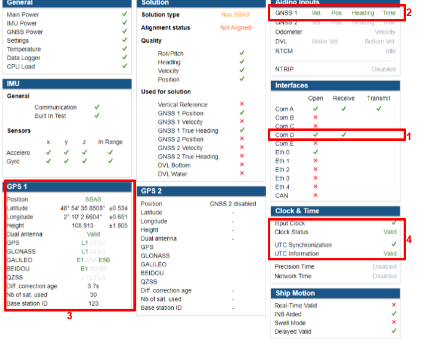
- Corresponding COM port must be opened and Rx flag OK. Baudrate should be the same in the GNSS and the SBG unit configuration.
- GNSS 1 or 2 line in “Aiding Inputs” section must show valid data.
- GNSS solution is reported in that section. Check if there is a good GNSS fix here.
- Then you can check at the Clock section. Input clock must be OK and UTC time should be set to valid after a few minutes in alignment mode.