Download PDF
Download page External u-Blox GNSS integration.
External u-Blox GNSS integration
This brief document guides you in the process of connecting an external u-Blox GNSS receiver to your SBG High Performance product.
Use this document in complement of the “Operations” Operating Handbooks.
Step 1: GNSS and INS connections
The u-Blox receiver can be connected via RS232 to the INS. The Tx and GNS from the u-Blox have to be connected to any of the available Rx and GNS on the INS, but you might have to use a TTL to RS232 converter.
The 1PPS signal from the u-Blox should be connected to an available Sync In pin on the INS.
Step 2: GNSS module configuration
Basic operation - single antenna
The table values are configuration settings in the form of divisors, not the actual frequency. For example, setting UBX_NAV2_PVT to 1 means an output frequency of 5 Hz.
Configure the following outputs and output rates on your GNSS receiver:
| Parameter | Value |
|---|---|
| UBX-NAV-PVT | 1 |
| UBX-NAV-HPPOSLLH | 1 |
| UBX-NAV-SAT | 5 |
| UBX-NAV-SIG | 5 |
| UBX-NAV-STATUS | 5 |
| CFG-RATE-MEAS | 200 |
| CFG-RATE-NAV | 1 |
CFG-RATE-TIMEREF | 0-UTC |
| CFG-ITFM-ENABLE | true |
| CFG-ITFM-ANTSETTING | active |
| UBX_NAV_DOP | 5 |
| UBX_MON_RF | 5 |
Basic operation - dual antenna
RTK is not compatible with external u-blox F9P and X20P operating in dual antenna mode.
The two external u-blox receivers should be connected to each other, the Aux receiver will send messages to the Main receiver, and the Main receiver will send messages to the INS.
They should be configured to 460800 bps at least, with the following outputs:
| Main receiver parameter | Value | Aux receiver parameter | Value |
|---|---|---|---|
| CFG-RATE-MEAS | 200 ms | CFG-RATE-MEAS | 200 ms |
| CFG-RATE-NAV | 1 | CFG-RATE-NAV | 1 |
| CFG-RATE-TIMEREF | UTC | CFG-RATE-TIMEREF | UTC |
| CFG-ITFM-ENABLE | true | CFG-MSGOUT-RTCM_3X_TYPE1074 | 1 |
| CFG-ITFM-ANTSETTING | active | CFG-MSGOUT-RTCM_3X_TYPE1084 | 1 |
| CFG-NAV2-OUT_ENABLED | true | CFG-MSGOUT-RTCM_3X_TYPE1094 | 1 |
| CFG-NAV2-SBAS_USE_INTEGRITY | true | CFG-MSGOUT-RTCM_3X_TYPE1124 | 1 |
| UBX_NAV_RELPOSNED | 1 | CFG-MSGOUT-RTCM_3X_TYPE1230 | 1 |
| CFG-NAV2-OUT_ENABLED | true | CFG-MSGOUT-RTCM_3X_TYPE4072_0 | 1 |
| UBX_NAV2_DOP | 5 | ||
| UBX_NAV2_PVT | 1 | ||
| UBX_NAV2_SIG | 5 | ||
| UBX_NAV2_SAT | 5 | ||
| UBX_NAV2_STATUS | 5 | ||
| UBX_MON_RF | 5 |
PPS signal
For proper operation, the 1PPS signal from the u-Blox needs to be connected to a Sync In pin on the INS. The 1PPS fom u-Blox is named Time Pulse (TP).
Configure the following settings for the Time Pulse on your GNSS receiver to have it at 1Hz with a rising edge:
| Parameter | Value |
|---|---|
| CFG-TP-PULSE_DEF | 1-Freq |
| CFG-TP-PULSE_LENGTH_DEF | 1-Length |
| CFG-TP-FREQ_TP1 | 1 |
| CFG-TP-LEN_TP1 | 1000 |
| CFG-TP-POL_TP1 | 1 |
Adding post-processing capability
The following additional message configuration is required for post-processing.
| Parameter | Value |
|---|---|
| UBX-RXM-RAWX | 5 |
| UBX-RXM-RTCM | 5 |
| UBX-RXM-SFR-BX | 1 |
Step 3 : Sensor configuration
In order to configure the Sensor, you need to connect to the Web interface and open the configuration window. Simply follow those instructions:
Set aiding assignment
In this window, you just indicate where you connected your GNSS receiver.
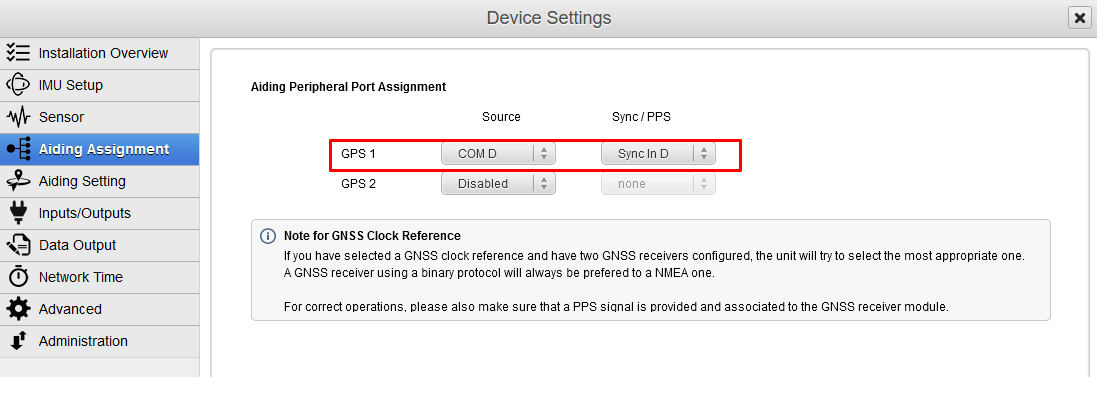
Both communication port and Sync In pin must be set.
If you have two connected GNSS receivers, only the primary GNSS receiver should provide a PPS source to accurately time stamp the data.
Set correct baudrate and mode for serial port
In our example we configured the GNSS to be connected on PORT D in RS‑232 mode using a baudrate of 460800 bauds.
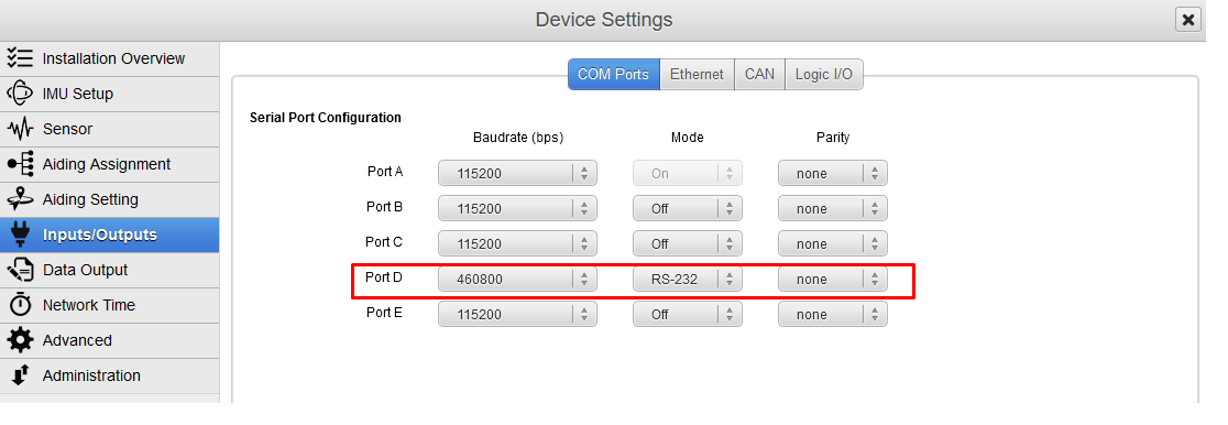
Post Processing messages contain a lot of packets, sufficient baudrate speed should be then selected. We recommend a speed of 460800 bauds in that case.
Set logic input configuration for PPS signal
In order to use correctly PPS signal information, you must enable the corresponding logic input. Here we configured PPS on Sync In D.
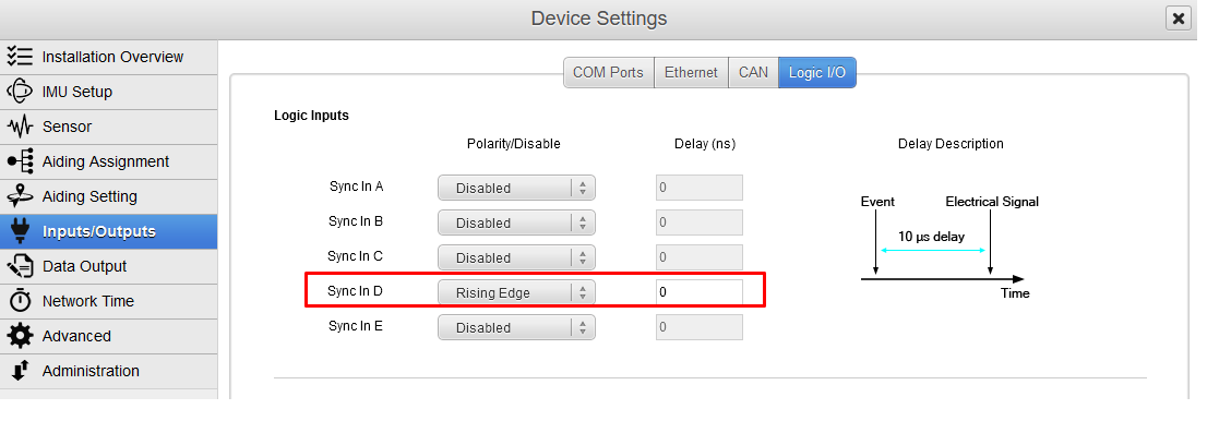
Polarity should be set accordingly with the actual PPS signal which is provided by your GNSS receiver (rising edge or falling edge), we configured it to rising edge for this example.
Set correct GNSS model and configuration
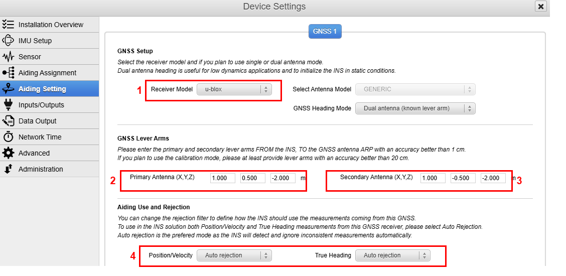
GNSS model should be set to u-Blox.
GNSS Primary lever arm has to be entered within a 1 cm accuracy FROM the IMU reference point, TO the antenna reference point (ARP), in the vehicle frame.
In Dual Antenna (known lever arm) mode, offset for the secondary antenna (providing heading) must also be entered, FROM the IMU reference point, TO each antenna reference point. It is also possible to select Dual Antenna (auto lever arm) if a calibration is planned for the antennas lever arms.
Finally, each available measurement (position/velocity and true heading if available) should be configured to be used or not. Auto rejection mode is recommended.
If you cannot measure the lever arms to 1 cm accuracy, a calibration can be performed. See Lever Arms Calibration Procedure.
Step 4 : Checking status
Once fully configured, the global status must be checked :
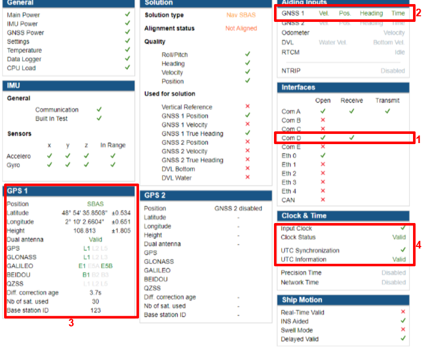
- Corresponding COM port must be opened and Rx flag OK. Baudrate should be the same in the GNSS and the SBG unit configuration.
- GNSS 1 or 2 line in “Aiding Inputs” section must show valid data.
- GNSS solution is reported in that section. Check if there is a good GNSS fix here.
- Then you can check at the Clock section. Input clock must be OK and UTC time should be set to valid after a few minutes in alignment mode.