Download PDF
Download page Real-Time Vibration FFT Monitoring.
Real-Time Vibration FFT Monitoring
The release of firmware 5.5.3789 introduced a new internal feature developed to use 4kHz sampling rate of IMU output in order to provide FFT analysis informations and allow internal monitoring tool to assess INS product vibration environment.
This is available on latest Hardware revisions of products Ekinox Micro, Quanta Micro, Quanta Plus, and Quanta Extra — running firmware version 5.5 or above and our IMU series Pulse40 and Pulse80 running firmware version 2.0 or above
Why monitor vibration into an IMU
Anyone who has used an IMU (Micro-Electro-Mechanical Inertial Measurement Unit) in a harsh environment knows that vibrations and acoustics must be carefully considered.
MEMS sensors are based on internally vibrating mechanical elements. This creates two main effects:
- Performance degradation under vibration: Exposure to vibration can degrade IMU accuracy through what’s known as Vibration Rectification Error (VRE) or Vibration Rectification Coefficient (VRC). For high-precision applications such as surveying or dead reckoning, these errors can have a major impact.
- Resonance effects: Since the sensor itself vibrates, if the vibration frequencies of the vehicle match the sensor’s internal resonance frequencies, the IMU readings can become disturbed.
These effects are often key considerations during early design phases. Significant effort is typically spent on complex vibration and acoustic simulations—which only partially predict real-world behavior. Ultimately, expensive test campaigns using dedicated monitoring equipment are needed to validate these simulations, and we’ve seen firsthand that even the most thorough simulations cannot fully replicate real-world conditions, resulting in some of our customers having integrated our IMUs in environments far harsher than originally designed —up to 30 g RMS conducted vibrations and 150 dB acoustics.
Adding external monitoring device during the development phase is always a good practice but not perfect since it will never fully reflect what the IMU is experiencing:
- location of the measurement is offset.
- change of mass/setup forced by the external monitoring device will change result.
To address this, we have integrated an innovative vibration monitoring feature directly into our IMUs and GNSS-aided Inertial Navigation Systems (GNSS/INS).
Our systems now provide real-time vibration analysis, including a full spectrum report and a synthetic report.
Technical Characteristics
The built-in vibration monitoring module operates fully embedded within the IMU/INS, ensuring real-time performance without additional hardware. Its key specifications are:
- Bandwidth: up to 8 kHz (depending on the IMU model).
- Dynamic range: up to 40 g RMS (depending on the IMU model).
- Time synchronization: vibration reports are timestamped using the IMU clock for easy analysis.
- Fully embedded: all FFT computations are performed onboard.
- Update rate & resolution: vibration reports are generated every 0.25 s, with a 4Hz resolution.
- Window configuration: users can select from multiple FFT window modes — Flat Top, Hanning, or Rectangular with a variety of trade off between amplitude, accuracy and frequency leakage.
This enables detailed vibration analysis directly at the IMU location, allowing users to correlate inertial noise behavior and IMU performance with actual mechanical excitation levels. For instance, real-time FFT data can be used as an additional metrics, on top of the IMU Continuous Built in Test (CBIT) to reveal mounting resonances or harmonic excitations that coincide with changes in accelerometer noise or gyroscope bias.
Enabling & recording of Vibration Monitoring messages
General description of sbgECom messages
Two messages have been created to provide FFT analysis informations: “Vibration FFT” and “Vibration Report”. Their complete description can be found in sbgECom library for messages [SBG_ECOM_LOG_VIB_MON_FFT] & [SBG_ECOM_LOG_VIB_MON_REPORT] .
Recording of Vibration Monitoring messages
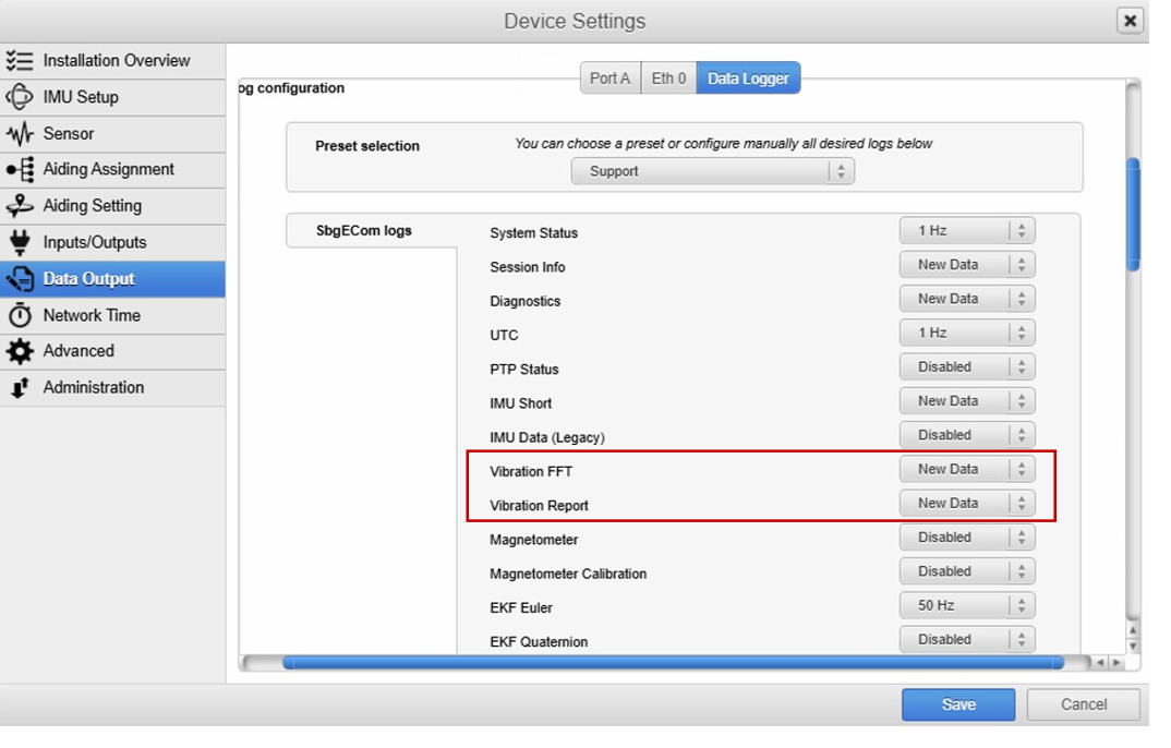
In the configuration of the port's Data Output content, add the two message below :
Decoding and recovery of Vibration Monitoring messages
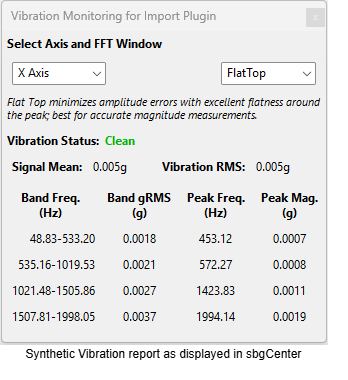
User Friendly simplified Vibration report
The Vibration report messages can be read using sbgCenter Application by simply importing the sbgECom logs and then click on Vibration Monitoring icon.
Advanced Analysis option
The Vibration FFT message can be extracted to a CSV format using the sbgBasicLogger tool on our GitHub page or else use the sbgECom C libraries to parse directly the binary messages to your preferred applications.
Using sbgBasicLogger simple command line
sbgBasicLogger -i <BINARY_FILE> -wThis will create many ascii files (here below on a record 20251010_VibTest.000 )
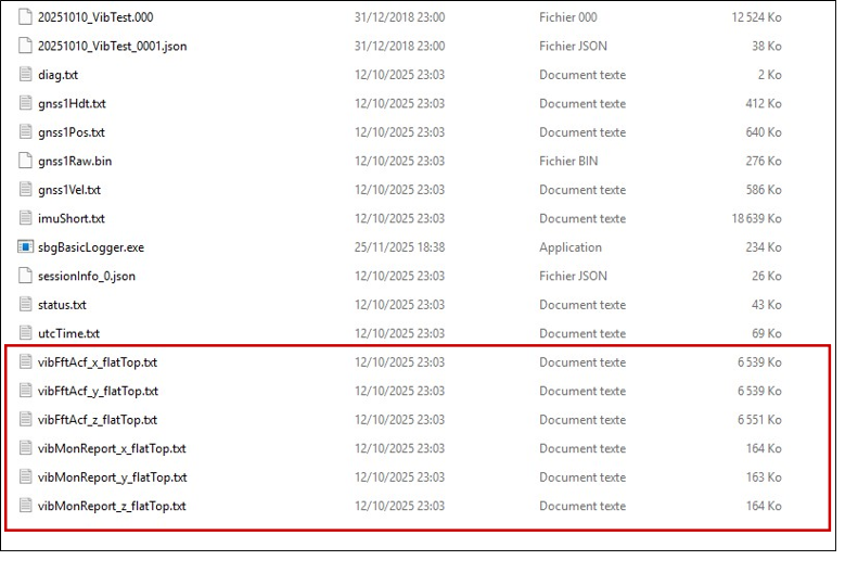
3 files vibFftAcf_'flatTop' and 3 report files vibMonReport_'flatTop'
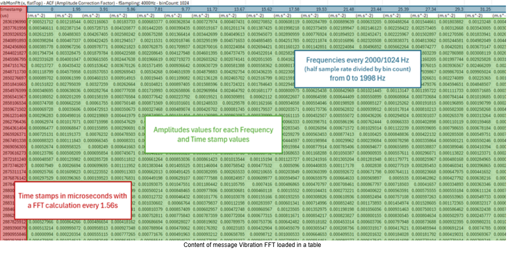
Vibration FFT data
For each axis X, Y, Z, a typical message sample is as follows (Axis X in the example below):
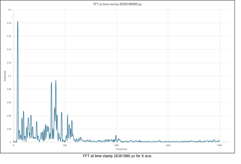
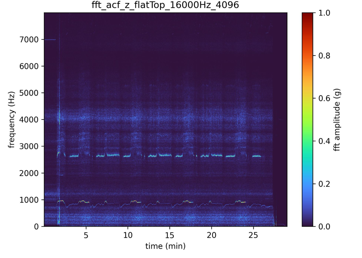
Spectrum Display using a simple python script from the sbgECom page.
python plotVibMonFft.py vibFftAcf_x_flatTop.txt
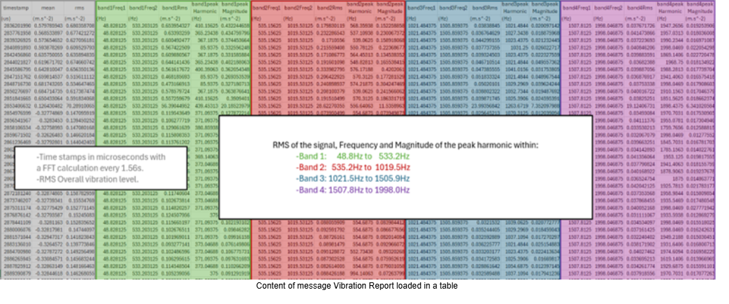
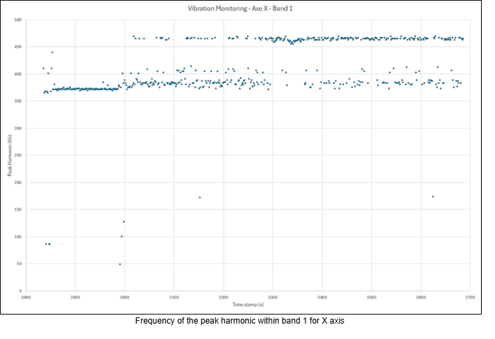
Vibration Report Data
For each axis X, Y, Z, a typical message sample is as follows:
Use cases
The vibration monitoring feature can be used in many ways—and we expect our customers will find even more. Here are a few examples:
- Design-phase vibration analysis: During vehicle design, the feature helps optimize IMU mounting. Measuring vibrations directly at the IMU allows engineers to choose the best location, tune dampers, and design acoustic protection—without adding heavy or expensive external sensors.
- IMU Qualification on shakers: The vibration monitoring can be used during the qualification of an IMU or INS when subjecting them to vibrations (Random or sweep), allowing to confirm that the vibration measured match the vibration injected (transfer function) ; and can be used as a tool to discriminate whether a resonance is linked to the shaker, the setup or the IMU.
- UAV and Aerospace Systems: Vibration monitoring can be used to detect resonance modes for rotorcraft or turbine, engines and validate payload isolation when the IMU is mounted on a gimbal or stabilized platform.
- Ground Vehicles: SBG INS are often used on ground vehicles for georeferencing (Mobile Mapping). The FFT can be used in innovative ways in this context: vibration data could be used to analyze road conditions or classify terrain types.
- Mission-related Built-In Test (BIT): In harsh operational environments, excessive vibration often indicates faults such as engine failure, gain control issues, or aerodynamic instability. The built-in monitor can detect these anomalies in real time, without the need for additional sensors.
- Structural Health and Modal Analysis: the FFT vibration data can be used to refine modal analysis—detecting shifts in resonant frequencies that indicate potential structural fatigue, loosening, or material degradation over time. This transforms the IMU into a dual-purpose sensor: both a motion tracker and a long term structural monitoring instrument.