The current documentation is preliminary and will be updated with the final release of the PULSE-80 with final information.
The PULSE-80 has been designed to meet the highest requirement in term of electro-magnetic compatibility. As such, the power supply and all digital I/O have been carefully designed. All electrical specification are given in the following tables.
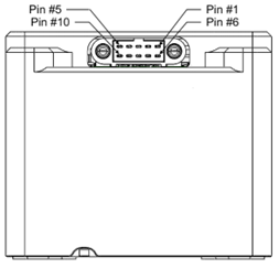
PULSE-80 Boxed
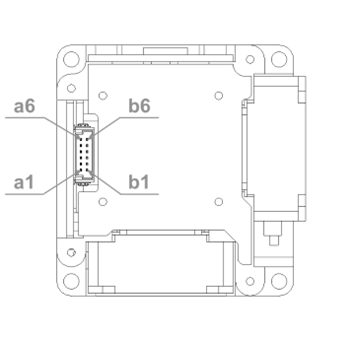
Connector Pin Assignment
The table below give manufacturer and model number of the recommended mating connector: