Download PDF
Download page Magnetic calibration for airborne applications.
Magnetic calibration for airborne applications
When magnetometers are used as heading reference, a magnetic calibration is mandatory for normal sensor operation. Different calibration methods are provided, depending on accuracy or ease of use requirement.
Light UAV calibration
As long as a UAV (fixed or rotary wings) is light enough to be held by a few people, a 3D calibration, made on the ground is to be preferred. The basic procedure is the following:
Install the sensor as described in previous sections, and place the whole system away from external magnetic disturbances (buildings, other vehicles, etc)
Press “Start acquisition” button on sbgCenter calibration window
Rotate the system as much as possible . The main point is to cover the whole flight profile, but a larger amount of points, beyond the flight profile will provide even better results.
Press “ Calibrate ” and check calibration results. Press “ OK ” to finalize the calibration procedure.
Power cycle the sensor if you need immediate operation after calibration.
Airplanes, Helicopter and large UAV applications
In flight 3D calibration
This calibration will give the best results as it allows to map the magnetic field in real 3D so that magnetometers readings are kept consistent even during turns and pitching.
In order to perform the calibration procedure, user can use the integrated sbgCenter calibration tool, or a data-logger to store the “magnetic calibration data” outputted by the Ellipse during calibration procedure.
Procedure
Once the aircraft is in steady flight at a reasonable altitude, the goal is to cover different orientations which are representative of the flight domain of the aircraft.
The calibration accuracy does not depend on any precise orientation (facing true North for example) and rather depends on how many significantly different orientations have been covered. The calibration algorithms are able to map the 3D magnetic field in orientation that have not really been covered during calibration; however, it is good to cover the full flight domain to get the best results.
For example an Extra 300 aerobatic airplane should get the best results by performing several representative aerobatic maneuvers in different directions in order to get a good 3D coverage of the magnetic field. In the other hand, a Cessna 172 private airplane could only perform high inclination eights to get optimal results.
Procedure tested on a private airplane
The following procedure has been tested with success on a piston private airplane.
The calibration starts in a steady flight. Two 360° turns will be performed decomposed in the following steps:
Step 1: Calibration Start. Press “start acquisition” button.
High bank right rolling – without turning.
High bank 120° left turn
Step 2:
High bank right rolling – without turning.
High bank 120° left turn
Step 3:
High Pitching: +20° then -20° then return to level flight
High bank right rolling – without turning.
High bank 120° left turn
Step 4:
High bank 120° right turn
Step 5:
High bank left rolling – without turning.
High bank 120° right turn
Step 6:
High Pitching: +20° then -20° then return to level flight
High bank left rolling – without turning.
High bank 120° right turn
Step 7: Calibration end. Press “ Calibrate ” button, then “ OK ” button write the calibration data to your sensor.
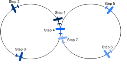
Figure 1: Trajectory performed during calibration
Once these tests are done the calibration can end. It is not crucial to perform exact 120° turns, but the procedure should perform rolling points at significantly different headings. In addition the pitching in the first turn should not be performed at the same heading as the one done in the second turn.
This procedure can be easily transposed to rotor-craft. The procedure can be performed in a stationary flight, by making several pitching and rolling maneuvers at different heading values. The goal is to expose the sensor to as much orientations as possible.
Ground calibration (2D)
Although this method is not the most accurate, it's possible to calibrate the magnetometer on the ground, using the “2D” calibration method.
The procedure is really simple and only requires a few steps on the ground to be performed:
Install the sensor as described in previous sections, and place the whole system away from external magnetic disturbances (buildings, other vehicles, etc).
Place the aircraft on a horizontal platform. The aircraft must be kept horizontal (in its line of flight level). This is the case with most tricycle landing gears airplanes, but this should be a concern with conventional landing gears.
Calibration Start. Start the sbgCenter calibration tool and press “start acquisition” button.
Perform a 360° circle with the aircraft. The calibration mode has to be set on “2D”. The aircraft should be at least 10m away from any metal building or other aircraft.
Calibration end. Press “Calibrate” and check calibration results. Press “OK” to finalize the calibration procedure.
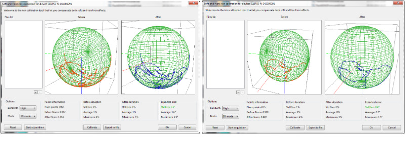
Calibration result examples
On the following screen-shots, it is possible to see that the calibration coverage is not a full 3D sphere but covers significantly different orientations. The first screen shows an example of the calibration procedure explained above. The second one shows a calibration only performed with a simple “8” performed.
Please click the link for more information about Magnetic calibration.