Download PDF
Download page Creating your first Project.
Creating your first Project
Introduction
This guide explains how to create, process, check and export an APOGEE-D Inertial Navigation System. The APOGEE-D has stored the mission data in it's internal datalogger and we will use Qinertia to post process a tightly coupled INS solution. Qinertia will pickup and download automatically the nearest and best GNSS base station as well as all necessary files to successfully process the mission.
Before you start
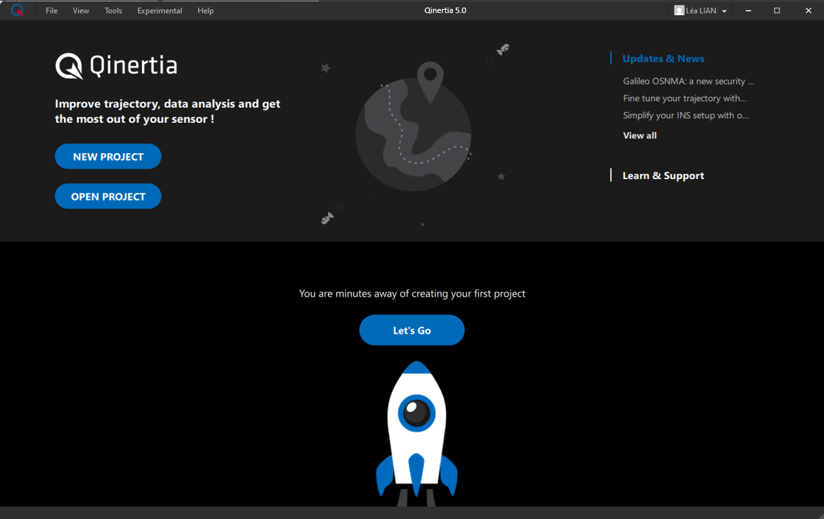
When you start Qinertia for the first time, you should see an empty welcome screen as shown below. Later, this welcome screen will filled by all the projects you have created and processed.
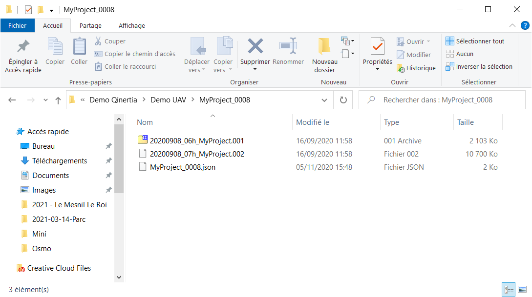
If you have used a high performance SBG Systems INS that has a build in data logger, you should have one directory for each acquisition. Each directory should contain a JSON file as well as one or more data files.
The JSON file contains the INS configuration and each data file stores one hour of high frequency IMU data, the RAW GNSS observables, real time GNSS PVT, odometer, event markers, etc
The screenshot below shows a typical recording from a SBG Systems INS that contains two data files.
Importing Data
Qinertia comes with a project creation wizard that will guide through all steps to import, review and setup a new project. Just click on the New Project or Let's Go button to start the project creation wizard.
Project Creation
This first step is to drag & drop or select manually where the acquisition files are.
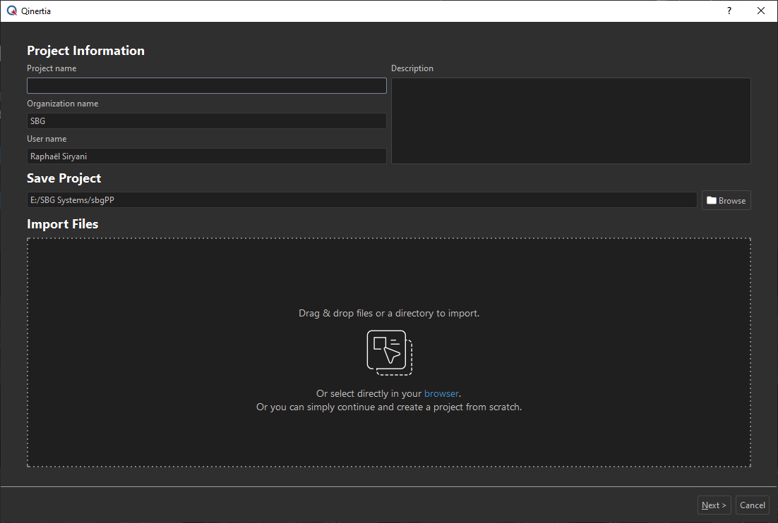
Qinertia will automatically scan the selected files to detect the project type. In our case, Qinertia has detected an SBG Systems INS project and has successfully parsed the device configuration and filled automatically the acquisition name. You can fill up some basic administrative information and once ready click the next button.
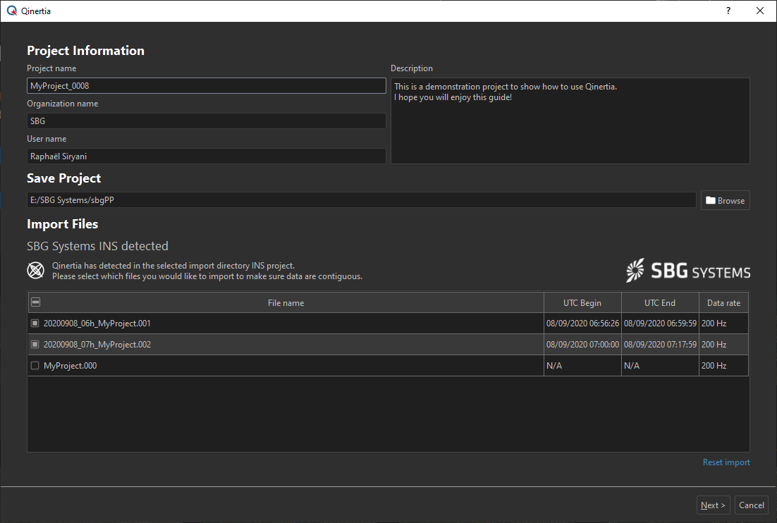
You can either drag & drop the whole acquisition directory 'MyProject_0008' in our example or directly the JSON file.
Motion Profile Selection
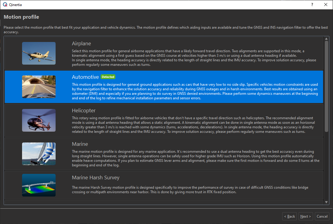
The next page is used to select the motion profile that best fit your application. The motion profile tunes the GNSS and INS navigation filters to deliver an optimal solution. It also defines which aiding data can be imported in the project. For example, you can't have odometer (DMI) data for a boat obviously.
Qinertia has read the INS configuration and has selected automatically the motion profile that was setup in the INS. You can review it and even change it if you have incorrectly setup the INS for example.
Data Source Selection
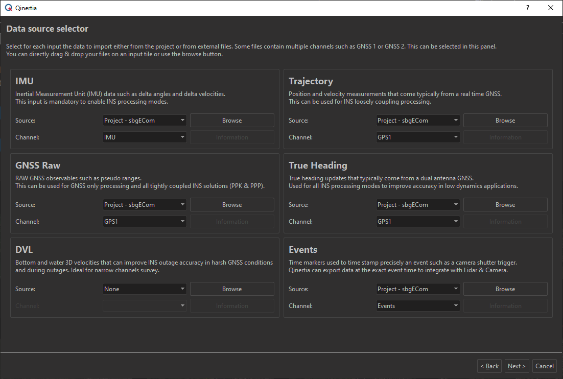
The next panel is used to review and adjust, for each input (IMU, GNSS, True Heading, etc), which data to import from which source.
SBG Systems INS accept up to two GNSS receivers and each one can provide real time GNSS PVT (Position, Velocity, Time) data as well as RAW GNSS observables. You can select in this panel if you would like to import data from the GNSS 1 or GNSS 2 for example. You can also decide to import data from an external file such as importing a RINEX file from an external GNSS receiver.
In our example, we will just leave default selection and click on the next button.
Data Import
Once you have validated the data source step, Qinertia will start to actually convert and import data. This operation can last for a few seconds or more depending of how much data you import and most importantly the type of data you are importing. For example, importing RINEX data takes much more time than reading native GNSS RAW binary files.
When Qinertia has imported the data, you will be directly redirected to the next step used to review and validate imported data.
Checking Imported Data
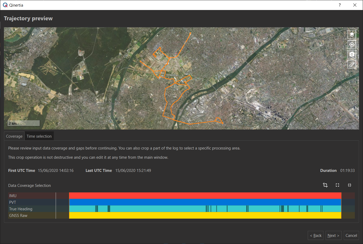
This panel displays graphically a preview of the imported trajectory. This trajectory is only based on real time GNSS PVT if available. If not, Qinertia will try to compute automatically a rough single point GNSS solution.
Below the trajectory display, all imported data coverage is displayed graphically. You can very easily make sure all the inputs are overlapping nicely and check for any hole/gaps or missing data.
Qinertia will display some warning or even errors if data gaps are detected. This is especially applicable for IMU data that should not have any gap.
On there other hand, as you can see on the screenshot below, the True Heading channel is exhibiting some data gaps. This behavior is expected as the GNSS receiver doesn't return any data at all if no valid true heading solution could be computed due to poor GNSS reception.
Finally, in this panel, you can easily crop the log by adjusting graphically or numerically the first / last time stamp that will be processed.
Setup GNSS Augmentation
This step is probably the most interesting one as you can review and adjust how Qinertia will improve the GNSS accuracy and which processing mode will be available.
Qinertia offers several processing modes to reach optimal positioning accuracy such single base PPK, Virtual Base Stations (VBS) or even Precise Point Positioning (PPP). The software will try to find the best solution based on available base stations and GNSS data.
If you have an internet connection, Qinertia will first try to find and download all surrounding base stations from CORS (Continuously Operating Reference Stations). Based on available base stations and quality, Qinertia will pickup the best option whereas it could be single base, VBS or even PPP if none of the previous processing modes are applicable.
Of course, you can still manually add, remove, edit base stations by simply drag and dropping base station data. For more information, please read the dedicated page Base Stations Management.
In our example, we just let Qinertia download automatically the surrounding base stations. We can see the base stations SBGS, that is part of the IGN RGP network, is available and next to our trajectory. Qinertia has decided to use only this base station so we will be computing a single base station PPK solution.
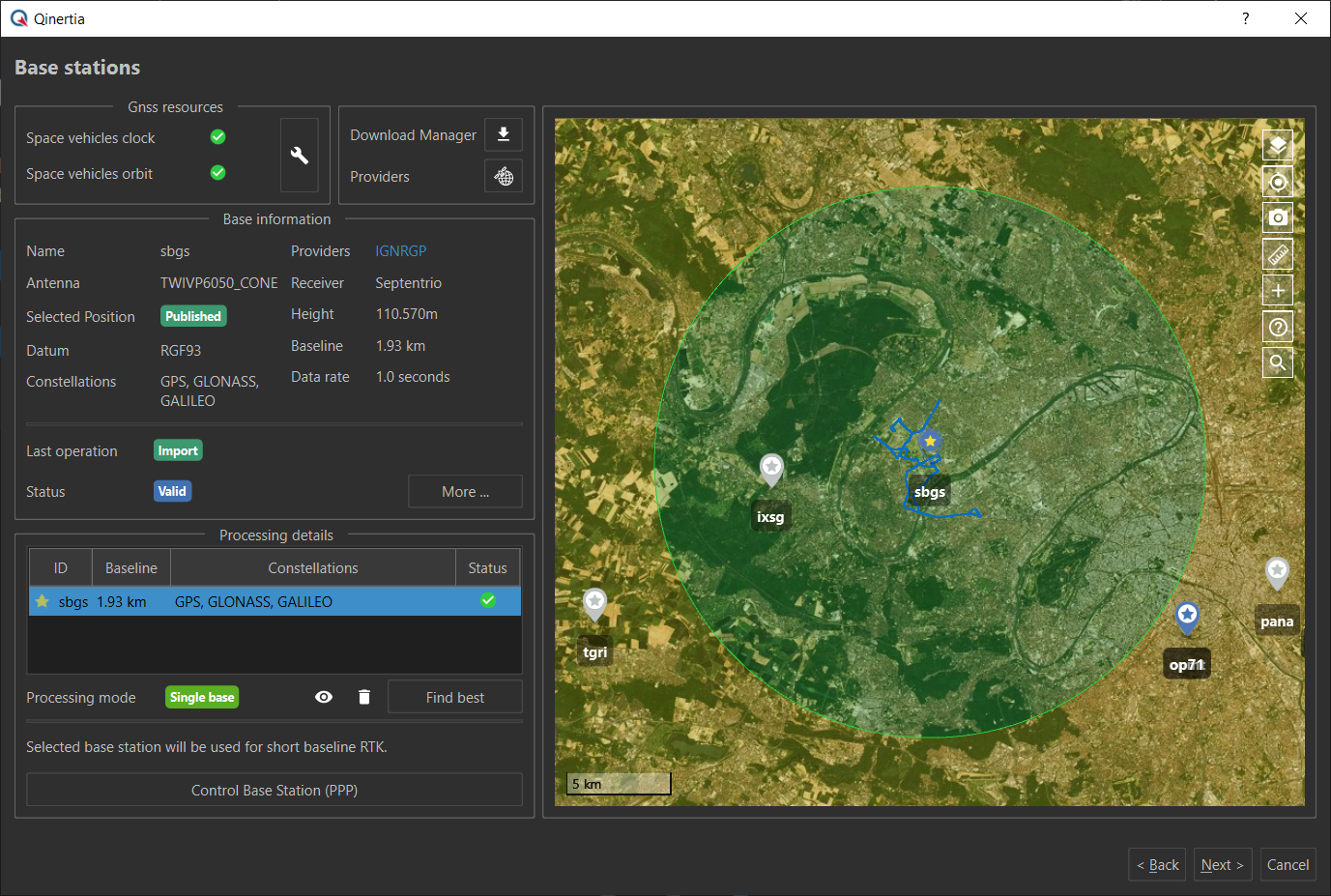
When you are happy with this selected processing mode and base stations, you can click on the next button to now review the INS configuration.
Completing Project Creation
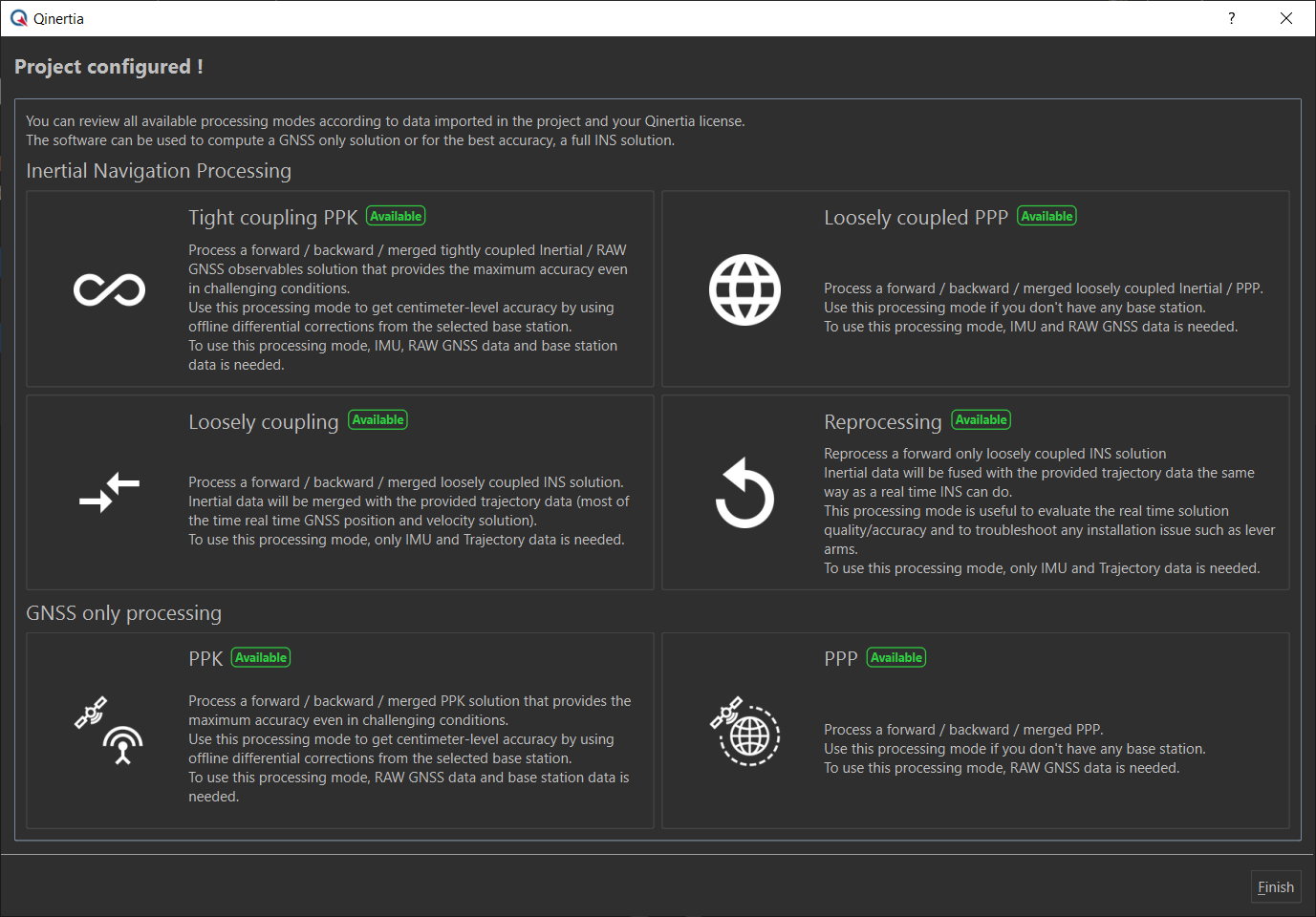
This last panel give you an overview on all the available processing modes based on available data, the project configuration and the license you have. You don't have to setup anything here, but just make sure the processing mode you are interested in is available.
Just click on the Finish button to conclude the project creation wizard.
You did it!
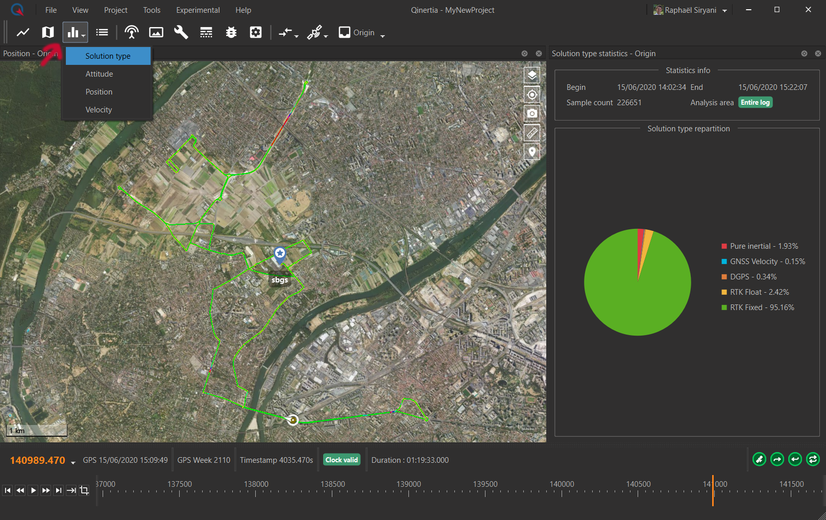
Congratulation, you have created your first project and can now review the real time data if you wish and plot any type of measure such as Euler angles, velocities, sensors, etc. In the screen below, we see the real time INS trajectory represented by a simple color code from green to red. In this example, we have also opened a pie chart representing the percentage of each solution type during the mission.
The next step will be to process the data to get the most out of your INS.
