Download PDF
Download page Interface specifications.
Interface specifications
Overview of the connectors
The Ekinox Micro connectors are all placed on the front panel. The connectors are referenced and identified by laser marking on the enclosure.
SBG Systems has selected high quality connectors designed for harsh environments. They offer an IP-68 protection when the plug is properly mounted.
To enable robust communication in harshest conditions, the different connectors feature a galvanic isolation.
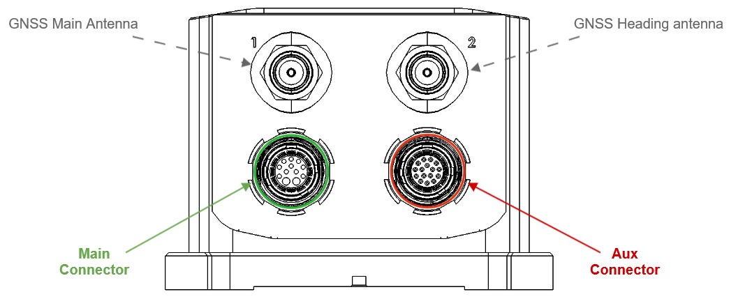
MAIN Connector
The main connector provides access to most Ekinox Micro features in a modular way:
- The Ethernet connector
- The main serial port (PORT A) that supports full-duplex communication. It operates in RS-232.
- Two multi-function input pins that can be used for:
- Clock synchronization or event marker input pins
- Single or dual channel Odometer input
- A Synchronization output signal for time stamping and to trigger some equipment.
Connector specification
| Connector | Manufacturer | Manufacturer P/N | Description |
|---|---|---|---|
| Main connector receptacle | ODU | GC0WDC-PD1QM00-000L | ODU AMC High-Density size 0 receptacle style C, series: W with 12-pos. socket-insert high-speed, print termination, green |
| Main connector mating plug | ODU | C10WDC-PD1MMM0-0000 | ODU AMC High-Density size 0 straight plug, screw-lock, series: W with 12-pos. pin-insert high-speed, solder termination, green |
Plug pin numbering
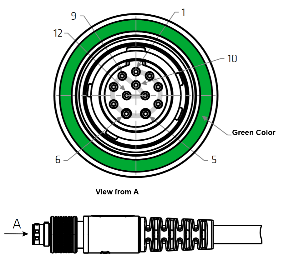
Pin out table
# | Signal | Type | Description |
|---|---|---|---|
1 | SYNC_OUT_A | Output | Synchronization Output A (RS-232) |
2 | SYNC_IN_A/ODO_A | Input | Synchronization Input A / Odometer Input A |
3 | ETHERNET_TX+ | Output | Ethernet TX+ |
4 | ETHERNET_TX- | Output | Ethernet TX- |
5 | VIN+ | Power Input | Power Input |
6 | VIN- | Power Ground | Power Ground |
7 | ETHERNET_RX- | Input | Ethernet RX- |
8 | ETHERNET_RX+ | Input | Ethernet RX+ |
9 | SYNC_IN_B/ODO_B | Input | Synchronization Input B / Odometer Input B |
10 | SGND_MAIN | Signal Ground | MAIN Connector Signal Ground |
11 | PORTA_TX | Output | PORT A RS-232 TX |
12 | PORTA_RX | Input | PORT A RS-232 RX |
AUX Connector
The aux connector provides access to additional Ekinox Micro features:
- Multiple serial ports (that come in addition to the RS232 serial on the main connector). Which can be configured in multiple combinations:
- 4x RS232
- 3x RS232 + 1x RS422
- 1x RS232 + 2x RS422
- One CAN 2.0A/B connection that supports up to 1 Mbit/s data rate used to output data
- Two synchronization input signals used for internal clock synchronization, data time stamping and/or event markers
- A Synchronization output signal for time stamping and to trigger some equipment.
Connector specification
| Connector | Manufacturer | Manufacturer P/N | Description |
|---|---|---|---|
| Aux connector receptacle | ODU | GC0WBC-P16QB00-000L | ODU AMC High-Density size 0 receptacle style C, series: W with 16-pos. socket-insert, print termination, red |
| Aux connector mating plug | ODU | C10WBC-P16MBC0-0000 | ODU AMC High-Density size 0 straight plug, screw-lock, series: W with 16-pos. pin-insert, solder termination, red |
Plug pin numbering
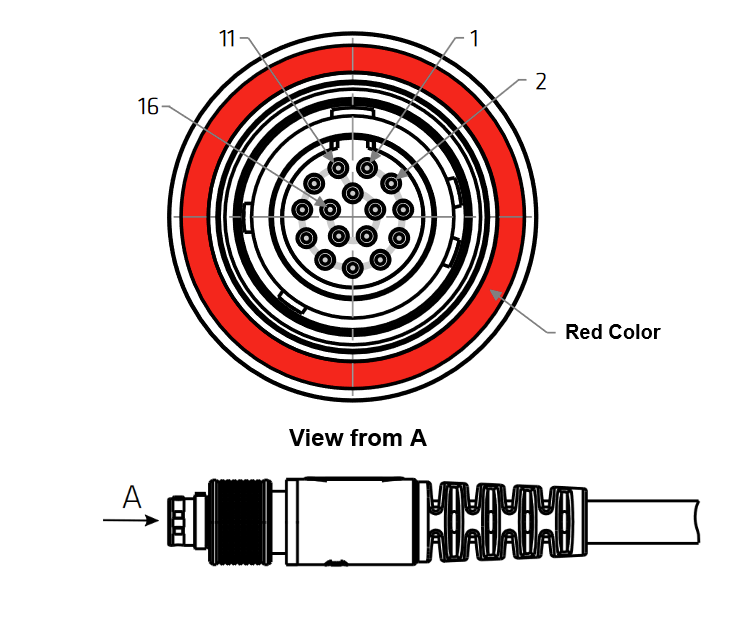
Pin Out table
# | Signal | Type | Description |
|---|---|---|---|
1 | PORTB_TX+ | Output | PORT B RS-422 TX+ |
2 | PORTB_TX-/TX | Output | PORT B RS-422 TX- or RS-232 TX |
3 | PORTB_RX- | Input | PORT B RS-422 RX- |
4 | PORTB_RX+/RX | Input | PORT B RS-422 RX+ or RS-232 RX |
5 | RESERVED | Reserved | Reserved for future use - Do not connnect |
6 | PORTC_TX+/PORTD_TX | Output | PORT C RS-422 TX+ or PORTD RS-232 TX |
7 | PORTC_TX-/TX | Output | PORT C RS-422 TX- or RS-232 TX |
8 | PORTC_RX-/PORTD_RX | Input | PORT C RS-422 RX- or PORTD RS-232 RX |
9 | PORTC_RX+/RX | Input | PORT C RS-422 RX+ or RS-232 RX |
10 | CAN_H | Bidirectional | CAN H |
11 | CAN_L | Bidirectional | CAN L |
12 | SGND_AUX | Signal Ground | AUX Connector Signal Ground |
13 | SYNC_OUT_B | Output | Synchronization Output B (LVTTL) |
14 | SGND_AUX | Signal Ground | AUX Connector Signal Ground |
15 | SYNC_IN_C | Input | Synchronization Input C |
16 | SYNC_IN_D | Input | Synchronization Input D |
GNSS Antennas Connectors
To connect an external GNSS antenna the Ekinox Micro includes two IP-68 rated SMA female connectors. The internal GNSS receiver only supports active GNSS antennas.
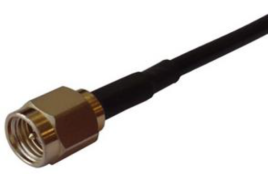
Please be advised that the Ekinox Micro doesn't implement any lightning protection. The GNSS antenna and cable are very sensitive to strikes and a proper installation with lightning protection devices may be required.
Interfaces functional specifications
Serial and TCP/UDP interfaces
Ekinox Micro integrates up to 4x serial UART interfaces as well as 5x TCP or UDP interfaces that can be used in a similar way. These interfaces can be used for configuration, data output and interfacing with third party equipment.
The following table summarizes the capabilities of each serial interface.
| PORT A | PORT B-C-D | ETH 0 | ETH 1-4 | CAN | |
|---|---|---|---|---|---|
| Configuration API | ● | ● | |||
| Data output | ● | ● | ● | ● | ● |
| RTCM input | ● | ● | ● | ● | |
| External GNSS / DVL input | ● | ● | ● | ● | |
| Odometer input* | ● |
*Please contact SBG Systems support@sbg-systems.com team for assistance on the integration.
Supported protocols
Ekinox Micro has been designed to be connected to a large range of aiding equipment. In addition to the native sbgECom binary protocol, other third party or standard protocols are also supported such as:
- NMEA
- RTCM
- TSS1
- Septentrio SBF
- Novatel Binary protocol
- Trimble GNSS protocol
- Third party ASCII outputs
For more information about protocols descriptions, please refer to the Firmware documentation.
Ethernet interface
The Ethernet interface brings various key functionalities to the Quanta Micro.
- Web page for configuration and real time visualization purpose
- 5x UDP / TCP/IP interfaces that can be used as additional bidirectional communication interfaces
- FTP server for datalogger access
- NTRIP client for easy RTK corrections input
- PTP / NTP time servers
Odometer integration
Odometers should be connected on ODO_A and ODO_B input signals.
Synchronization input and output
Sync In pins can be used to trigger external events and input external PPS information.
Sync Out A and B pins can be configured in the following modes :
- Main loop divider: This event is activated at the sensor sample time, but its frequency is divided by the output divider. If the divider is set to 4, pulse output frequency will be 200Hz / 4 = 50Hz.
- PPS: This simple output is synchronized with each top of UTC seconds. Validity should be checked by parsing the UTC messages status.
- Virtual odometer: This output generates a pulse each X meters of travel, depending on user configuration