Overview
The Ekinox Micro enclosure is composed of two anodized aluminum parts, one for the cover and one for the base plate. The device uses high quality alloys and connectors to offer a full IP-68 enclosure and a good resistance to harsh environments.
- The Ekinox Micro main and aux connectors are high quality connectors that offers IP-68 protection even unconnected.
- The Ekinox Micro also includes two SMA connectors to connect the GNSS antennas. When used with a waterproof GNSS antenna cable, this connector offers an IP-68 protection.
Specifications
| Item | Specifications | Remarks |
|---|
| Dimensions | Length: 59.5 mm Width: 57 mm Height: 41.5mm |
|
|---|
Weight | 165g |
|
|---|
| Enclosure materials / surface finish | Anodized aluminum | The base plate has a SURTEC finish for optimal mechanical grounding |
|---|
| Mounting Holes | 4 x Ø 3.4 mm, clear holes for M3 screws |
|
|---|
Please see the Environmental specifications page for full detailed environmental specs.
Sensor Coordinate System
Directions of sensors axes
The inertial frame is defined as a standard right-handed North, East, Down (NED) frame (X,Y,Z) as represented in the picture.
According to the “Right Hand Rule”, the rotations are positive clockwise in the axis direction as represented on the picture below.
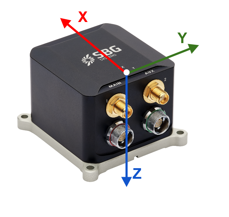
In most situations, the IMU coordinate frame must be aligned with vehicle coordinate frame. Sensor alignment in vehicle can be rotated by software if the sensor coordinate frame cannot be aligned mechanically.
Check our Operating Handbooks for more information on the product configuration.
Origin of measurements
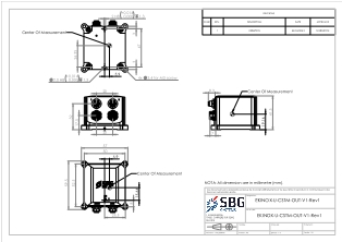
The center of measurement for acceleration, velocity and position is represented on the mechanical outlines by the  symbol. It is referenced to the base plate fine alignment hole and to the cover reference frame center mark.
Mechanical Drawing
CAD Models (STEP file)
 EKINOX-U-CSTM-OUT-RevA.zip
Equipment mounting
The Ekinox Micro units shall be rigidly mounted on a flat surface to the vehicle or platform for nominal operation. Precise alignment can be performed using 2 locating pins.
Please use an appropriate torque to ensure proper mounting.
Recommended fasteners
| Reference | Remarks |
|---|
| Recommended screws | 4 x TCHC DIN 912 M3 x 16mm Stainless Steel A4 recommended | Recommended torque : 1.15 N.m |
|---|
| Locating pins | 2x Misumi : SFSNT3-L2.0-P2.0-B2.0-H6.0-T1.0 | To be adjusted to user specific needs |
|---|
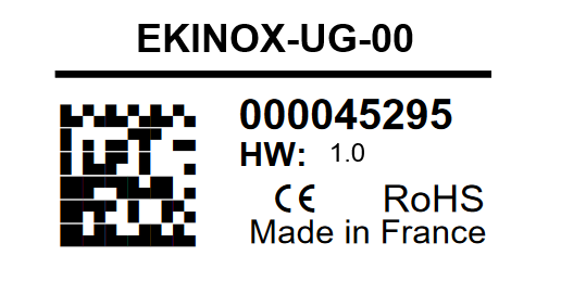
Label
SBG Systems manufacturing process is based on EN-9100 system with individual and full traceability of every component and operation. Each unit is identified by a unique serial number that can be used to trace all operations during the product lifetime such as manufacturing, calibration, tests and repairs.
In addition to a unique serial number, a product code is used to define exactly the device type, options, configuration. You can find on the side of the product a laser printed label that holds all these identification information. This label also includes a data-matrix code that encodes the device unique serial number.