Download PDF
Download page Inertial sensor installation.
Inertial sensor installation
Standard Installation
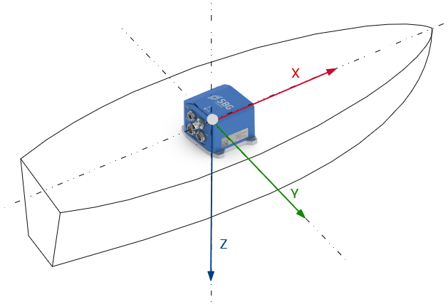
The normal orientation in the vehicle frame is to align sensor X axis to the vehicle forward direction. Sensor Z axis should be turned down.
When this mechanical alignment is not possible, the IMU misalignment with respect to the vehicle coordinate frame must be measured, as described in this link Accounting for misalignment
IMU typical placement in marine applications
As a rule of thumb, SBG Systems sensors can be placed anywhere in the vehicle. However, in case of large vehicles or vessels, we recommend to place the sensor within 10 meters around the Centre of Rotations.
In any case, the primary lever arm between the sensor and the Centre or Rotation must be measured within 5 cm accuracy. It is the signed distance FROM the sensor TO the Centre of Rotation, expressed in the vehicle coordinate frame.
A correct measurement will ensure optimal performance, and particularly in the following applications:
● Marine applications. The heave motion computation is dependent on a good lever arm measurement
● Automotive applications, where the main lever arm is used internally to take into account the motion constraints assumed in this type of application.
High Vibrations Considerations
SBG Systems has designed IMUs with high quality MEMS sensors combined with high sampling frequency as well as efficient anti aliasing FIR filters to limit vibration issues as much as possible. Nevertheless, a good mechanical isolation will ensure getting the full sensor performance:
High amplitude vibrations can cause a bias in accelerometer reading. Thanks to a superior factory calibration, this effect is limited. Nevertheless it cannot be fully avoided. This effect is called the VRE (Vibration Rectification Error) and comes from the internal accelerometer non-linearity.
Ultimately, very strong vibrations cause the sensor to saturate. The bias observed will be drastically increased, leading to a huge error on orientation.
Note: SBG Systems typically recommends a high accelerometer range to reduce the VRE effect for most application, except Marine application which need very precise acceleration measurement.
Warning: Heave and delayed heave computations is more sensitive to vibrations than other algorithms. When using the heave outputs, please take care to reduce as much as possible the vibration level to enable full performance.
Magnetic Consideration
When the internal magnetometer is used as heading reference, care should be taken with ferromagnetic environment.
Ferromagnetic materials or magnets that are placed in the vicinity of the device can generate error in the magnetometers readings by distorting the magnetic field. High current power supplies or the associated wires may also generate magnetic fields.
The sensor should be placed as far as possible from ferromagnetic materials, particularly those who can be moved independently with respect to the sensor. In practice placing the device more than 2 meter away from disturbing materials is enough to avoid generating error.
In most cases, a calibration procedure can be performed to map the magnetic distortions and therefore get the full performance of the unit. The calibration can compensate both Hard and Soft iron interference.
Field Magnetometer Calibration
See Hard & Soft Iron calibration Manual for more information about the magnetometers calibration procedure on this link Magnetic calibration
Unexpected Magnetic disturbances
Some disturbances cannot be predicted: a magnet passing suddenly near the device or a cell phone communication for example.
The internal EKF is able to cope with short term magnetic disturbances. Ultimately if magnetic field direction changed for a long period, the heading will be realigned to the new magnetic field direction.
When the internal magnetometers are not in use, the magnetic influence on performance is weak but very strong magnetic fields can affect gyroscopes performance and such high amplitude magnetic fields should be avoided.