Download PDF
Download page Mechanical Specifications.
Mechanical Specifications
Overview
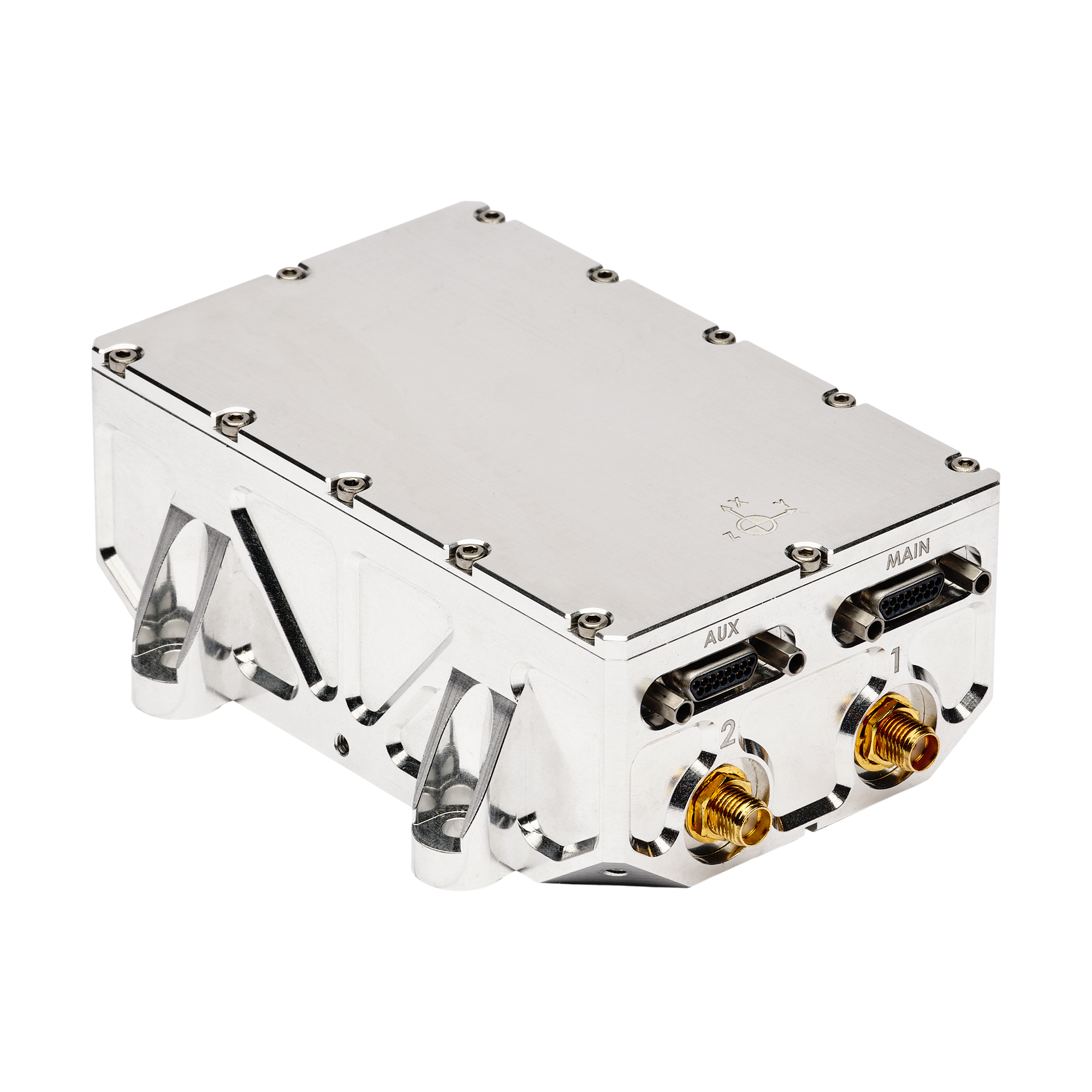
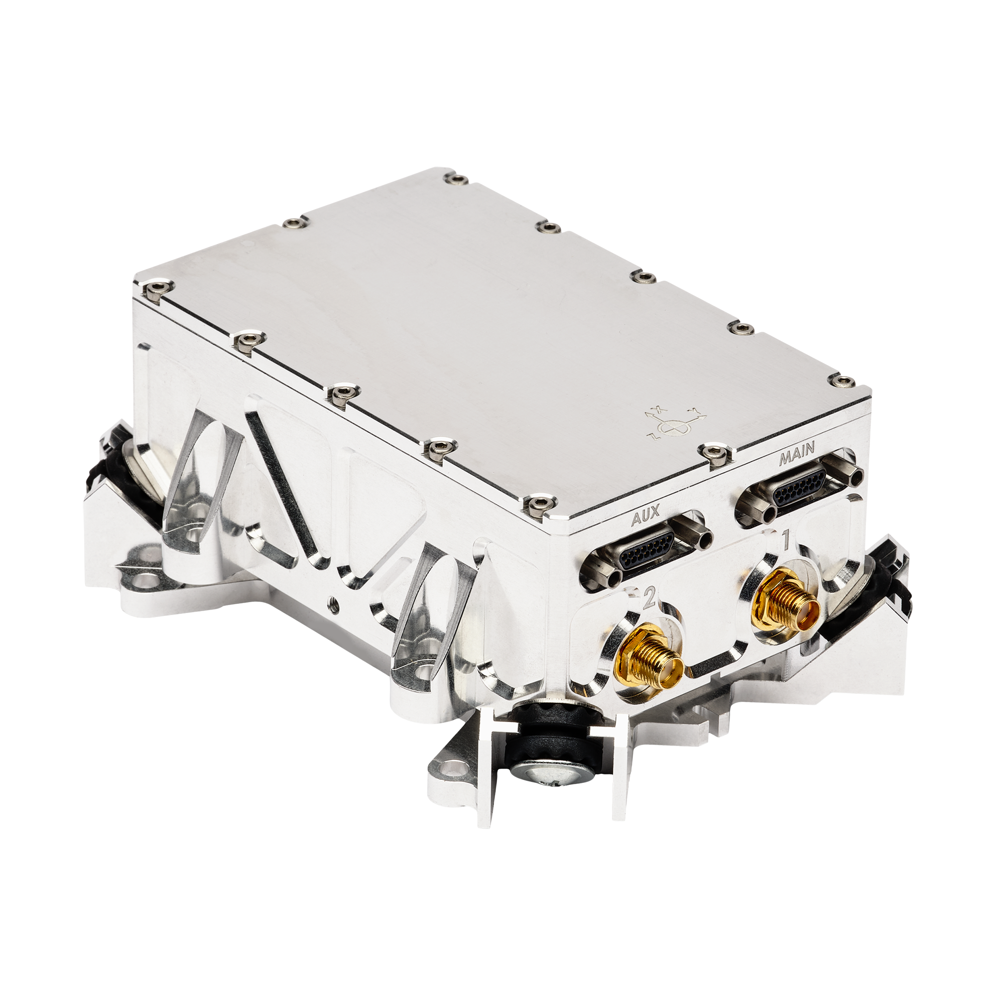
The Stellar-40 enclosure is constructed from aluminium with a SurTec coating and consists of up to three components: the main housing (base body), a top cover secured by screws, and an optional external damping system for high-vibration environments. It is equipped with connectors that provide high integration flexibility and seamless interoperability with standard external ecosystems.
- Main and Aux connectors: equipped with Micro-D 15 pin connectors.
- GNSS antenna connectors: includes two standard SMA connectors for interfacing with the primary and the optional secondary GNSS antennas.
Specifications
| Item | Rigid - without external damping | Damped - with external damping |
|---|---|---|
|
| |
| Dimensions | Length: 107.7 mm Width: 85 mm Height: 40 mm | Length: 125.6 mm Width: 88.5 mm Height: 49.3 mm |
Weight | 365g | 445g |
| Enclosure materials / surface finish | Aluminum with SurTec finish | Aluminum with SurTec finish |
| Mounting Holes | 4 x M4 screws | Max torque: 2.2 N.m | 4 x M4 screws | Max torque: 2.2 N.m |
Please see the Environmental specifications page for full detailed environmental specs.
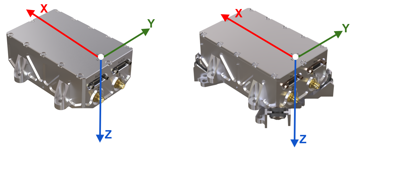
Sensor Coordinate System
Directions of sensors axes
The inertial frame is defined as a standard right-handed North, East, Down (NED) frame (X,Y,Z) as represented in the picture.
According to the “Right Hand Rule”, the rotations are positive clockwise in the axis direction as represented on the picture below.
In most situations, the IMU coordinate frame must be aligned with vehicle coordinate frame. Sensor alignment in vehicle can be rotated by software if the sensor coordinate frame cannot be aligned mechanically.
Check our Operating Handbooks for more information on the product configuration.
Origin of measurements
The center of measurement for acceleration, velocity and position is represented on the mechanical outlines by the ![]() symbol. It is referenced to the base plate fine alignment hole and to the cover reference frame center mark.
symbol. It is referenced to the base plate fine alignment hole and to the cover reference frame center mark.
Mechanical drawing & CAD models (STEP file)
| Product | Stellar-40 rigid - without external damping | Stellar-40 damped - with external damping |
|---|---|---|
| Mechanical drawing | STELLAR40-CUSTOMER DRAWING_drw-SBG-00002033_B.PDF | |
CAD Models (STEP file) |
Equipment mounting
The Stellar-40 units shall be rigidly mounted on a flat surface to the vehicle or platform for nominal operation. Precise alignment can be performed using 2 locating pins.
Please use an appropriate torque to ensure proper mounting.
Recommended fasteners
| Reference | Remarks | |
|---|---|---|
| Recommended screws | 4x DIN912 M4x14mm A2/A4-70 | Recommended torque : 2.2 N.m |
| Locating pins | - | 2x Øg6 - to be adjusted to user specific needs |
| Shielding braid | - | Only for damped version. For strong EMI compliance. |
Label
SBG Systems manufacturing process is based on EN-9001 system with individual and full traceability of every component and operation. Each unit is identified by a unique serial number that can be used to trace all operations during the product lifetime such as manufacturing, calibration, tests and repairs.
In addition to a unique serial number, a product code is used to define exactly the device type, options, configuration. You can find on the side of the product a laser printed label that holds all these identification information. This label also includes a data-matrix code that encodes the device unique serial number.