Download PDF
Download page Fixed-Wing UAV Operations.
Fixed-Wing UAV Operations
This operating handbook explains how to install and setup High Performance SBG products in Fixed-wing UAV application, Mechanical installation is explained as well as aiding & software configuration.
Mechanical installation
Fixed-Wing applications assume a 3D motion. The INS sensor can be located anywhere in the aircraft, considering the following recommendations:
- Sensor is rigidly fixed to the aircraft frame : avoid locations that may be bending like wings
- Sensor is not moving in regard to other equipment (antennas, LIDAR, etc...)
- Sensor is far from strong vibrations sources : avoid placing the sensor directly on the engine mounts.
- Sensor should be protected from high temperature variations.
- When relevant (if magnetometers are used), place the sensor away from magnetic disturbances like strobe lights, high current equipment, radios or moving parts like landing gears.
Note : SBG Systems IMU are designed to handle vibrations without specific care. Nevertheless in case of highly vibrating environment, a mechanical vibration isolation might be required for proper operation. Silicon or wire dampers can be used for that purpose.
Vehicle reference frame
The vehicle coordinate frame is defined as follows :
- X axis points to the front of the vehicle
- Y axis points rightward.
- Z axis points downward.
Note : The sensor can be placed in any orientation in the aircraft. When IMU axes do not match exactly with the aircraft coordinate frame, the rough and fine alignment parameters should be corrected through the configuration interface to realign the IMU and aircraft coordinate frames.
GNSS setup considerations
When installing your INS with a GNSS aiding, you will need to install the GNSS antennas with a clear view of sky, and fixed with respect to the IMU.
The GNSS lever arms shall also be measured, which are the signed distance, expressed in the vehicle coordinate frame, FROM the sensor center of measurements, TO the GNSS antenna.
We usually require these measurements to be precisely performed, within 1cm accuracy.
It's sometimes not practical to measure with such precision the lever arms, so SBG Systems is offering a lever arms estimation software that will help you estimate the lever arms using a data recording.
Single antenna installation
Single antenna installation is possible when regular dynamics are experienced and allow the heading to converge. Typical heading performance will degrade during straight lines but will remain stable and usable, and will re-converge during dynamic phases.
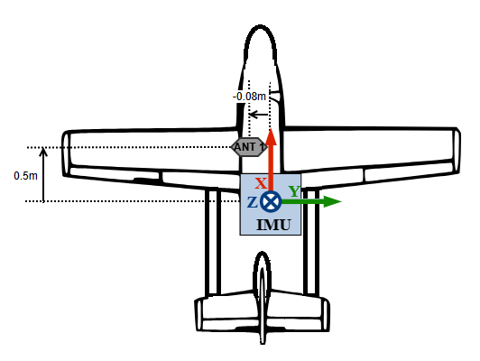
A single antenna installation with GNSS lever arm is shown below:
Vehicle frame (Forward/Right/Down) correspond in this case with IMU frame.
Lever Arm to enter will be : X=0.5m / Y=-0.08m / Z=0.21m (assuming the antenna is 21cm above the IMU)
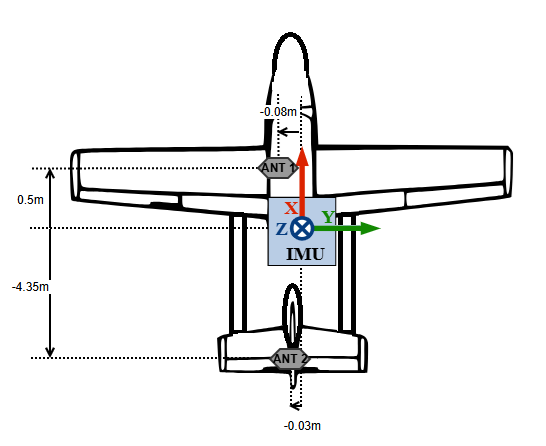
Dual antenna installation
Dual antenna could be beneficial on ground to initialize heading of the filter even in static condition. It can also improve the heading accuracy during extended straight lines with low dynamic.
However this requires a very good accuracy when providing Lever arm that only Lever Arm Estimation Software can provide.
Dual antenna systems installation will require special care in order to obtain optimal performance :
- The antennas must be fixed with respect to the to the inertial unit
- Same antenna type should be used
- Same cables with identical lengths must be used for both antennas. If Splitter are used make sure that they are adapted and with the same characteristics
- Both antennas must have the same view of sky. Typically avoid placing antennas on each side of the rudder or parts that could mask a significant part of the sky.
- Antenna must be use according to the manufacturer recommandation (an additional ground plane is often required).
- If antennas are not permanently installed on the aircraft, antennas reference marks (usually the connector position) should be mounted in a repeatable fashion in order to guarantee antennas phase center stability from mount to mount and minimize changes to heading misalignment angle.
Software configuration
All the configuration is done through the web interface. The General IMU configuration handbook details how to configure your INS, and especially the misalignment and lever arms configuration. Make sure to check it first.
We will see below the specific use cases that are related to the use of your INS for Fixed-wing UAV applications.
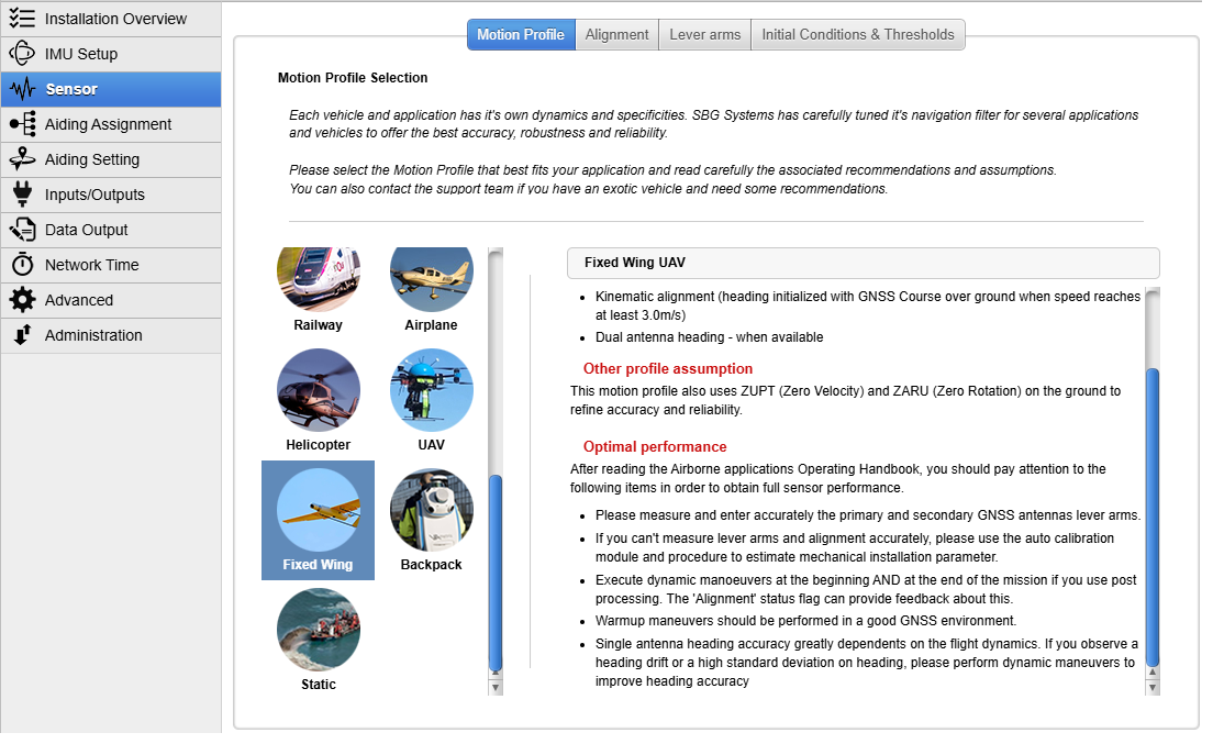
Motion profile selection
The Fixed-wing UAV motion profile (for any fixed wing mission with only forward movement) has been optimized to be able to sustain long GNSS outage in straight flight condition specifically for fixed-wing UAV application using external AirData aiding.
Aiding configuration
After configuring the misalignment and the lever arms of the INS, you should configure the aiding you will use:
- If you want to enable GNSS aiding, the Internal GNSS integration or External GNSS Integration pages detail how to enable and configure a GNSS receiver.
- If you expect GNSS outages, it is highly recommended to use an External Air Data aiding. This page details how to enable and configure the Air Data aiding. See below the GNSS outage preparedness chapter.
- If you have an external magnetometer for heading aiding, you can check the Magnetometer Integration page.
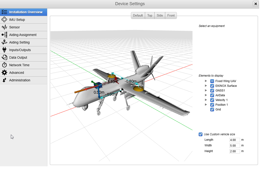
Installation Check
Once you have completed the product configuration, the Setup Overview section can help you to check if everything is consistent. It features a 3D display that can be modified by simply clicking on an item, then changing the orientation or lever arm values. Any change will be directly visible.
Operation and heading considerations
At power up, the unit is able to provide roll and pitch angles. Full navigation data becomes available once GNSS has a correct fix, and the system could initialize its heading.
For more information on initialization time, you can check the FAQs.
Single antenna systems
In single antenna, the Fixed-wing UAV motion profile uses the traditional kinematic alignment.
The heading is then maintained accurate during dynamic maneuvers, and may degrade during low dynamic or straight lines. If there is very limited dynamic for an extended period of time (straight line at constant speed), some dynamic maneuver might be required to re-converge heading to optimal performance.
Full details on kinematic heading alignment method may be found here.
If static initialization is required, please consider using an external magnetometer or a dual antenna GNSS.
Dual antenna systems
In case of a dual antenna GNSS setup, heading initialization can be performed in static. Unit should be started with a clear view of sky to prevent bad initialization of the GNSS true heading. Also this setup requires very accurate lever arms.
The system will maintain accurate heading in low dynamics as long as a good GNSS signal is available.
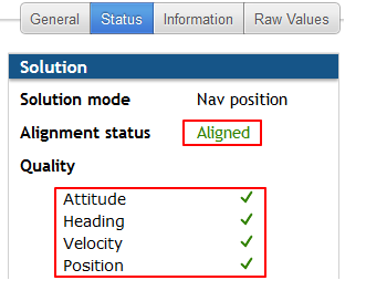
Warm-up (Alignment)
Once the system is operating in fully initialized, the alignment status can be used as an indicator to know when the Kalman filter has reached its optimal navigation performance. The system is operational before that time, with consistent quality indicators, but performance may not be optimal under challenging conditions like GNSS outages.
To reach the alignement status quickly, you can perform dynamic maneuvers. A dog leg maneuver, circle or “eight” figures will help.GNSS outage preparedness
If GNSS outages are expected during the mission. It is important that the INS has undergone a proper warmup phase to get the Aligned status in order to benefit from a better EKF accuracy before starting the outage.
Additional external aiding like Air Data aiding, Magnetometer, as well as Generic Velocity or Generic Position aiding, are highly recommended as they will mitigate the drift of EKF solution due to the outage therefore increasing duration of EKF stability.
Usage without warm-up phase
If, for your use case, you cannot perform a warm-up phase, the INS remains usable but with a lower accuracy during GNSS outages.
Don't forget to make sure the different quality statuses are setup according to your wishes and have switched to green (Attitude/Heading/Velocity/Position) once initialized.