Download PDF
Download page Configure Menu.
Configure Menu
Accessing and navigating the configuration menu
The web interface configuration menu can be accessed by clicking on the tooltip in the top right corner of the web interface (as seen below).

The configuration menu consists of the following tabs:
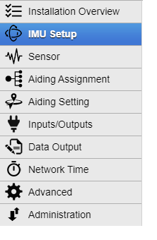
Installation Overview
The first window of the configuration menu displays a useful, 3D graphical representation of a vehicle with the INS and GNSS antennas, with the lever arms taken into account.
This is a helpful tool to visually verify that the lever arms configuration is correct.
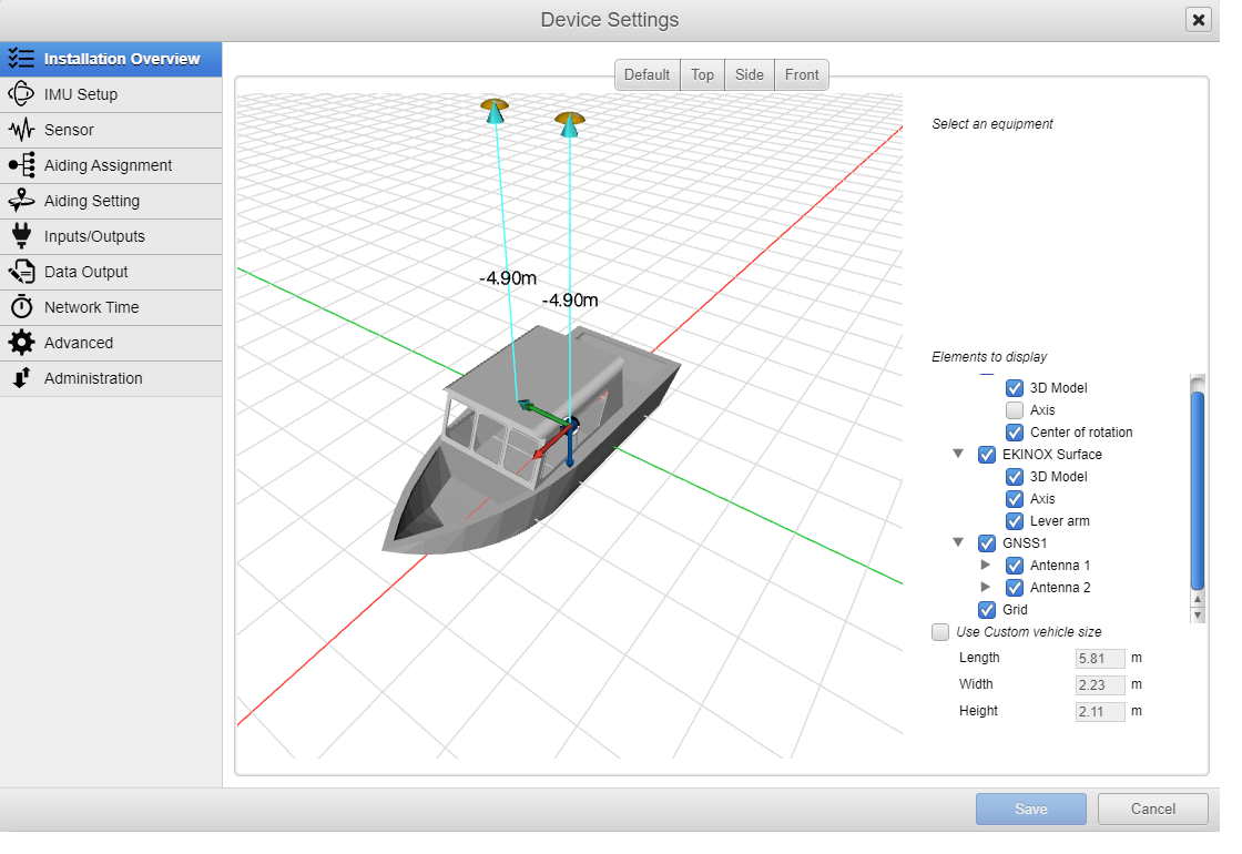
Vehicle displayed
The vehicle displayed will change depending on the motion profile selected.
IMU Setup & Sensor
These two menus let you configure how your INS is installed in the vehicle. Both menus are described thoroughly in General IMU configuration
Aiding Assignment & Aiding settings
The two menus are used to configure the different aidings (internal or external GNSS aiding, DVL, wheel odometry, airdata, Differential Corrections...).
One of the key aiding section is the configuration of the GNSS:
- To configure the internal GNSS, you can refer to the thorough step-by-step Internal GNSS configuration guide.
- To configure an external GNSS aiding: please refer to one of our guides dedicated for the various GNSS vendors supported (NMEA, Septentrio, Novatel, Trimble)
There are more specific articles to configure the following aidings:
- Odometer Integration - Configuration of a wheel-odometer aiding.
- DVL - Doppler Velocity Log Integration - Configuration of a wheel-odometer aiding.
- NTRIP Configuration - Configuration of a NTRIP differential corrections for RTK.
- Marinestar Configuration - Configuration of Marinestar PPP corrections.
Dynamic User Interface
The options presented in the User Interface automatically adjust to other parameters selected. For example, wheel based odometry will only be proposed if the motion profile selected applies to a land vehicle.
Inputs/Outputs
Enabling/disabling the various I/O, there are 4 tabs in this menu.
- COM Ports - where you enable/disable a port and select its baudrate. More details on UART baud rate and Output rate guide.
- Ethernet - where you configure the network interface and also enable/disable up to 4 ETH ports (UDP/TCP server/TCP client) and configure them. More detail on Network Configuration.
- CAN - where you enable/disabled CAN output bus mode and its bitrate.
- Logic I/O : Sync-In and Syn-Out events management is fully described in the knowledge base page Time synchronization and event management. Sync-In are usually used by an external GNSS input or camera event recording, while Sync-out are used to control an external device or send PPS to it.
Do not forget to check the I/O status on the Interfaces frame of the Status Tab after modifications.
Data Output
According to the previous menu where you enabled several COM/ETH/CAN ports, you can now select the various message data and its output rate for each port (each one will have its own tab)
- COM (Serial) and Ethernet ports Data Output configuration is described in the page Outputting data to other systems.
- CAN output of data & rate selection is described in the page CAN bus and outputs.
- DataLogger settings are explain in the page Data-Logging For Support Purpose.
Do not forget to check the I/O status on the Interfaces frame of the Status Tab after modifications.
Network time
This menu is used to setup NTP and/or PTP protocols. Full details on the page Time Synchronization
Advanced
This menu is used to setup the Altitude Mode (Normal or Enhanced) and to select the Clock Reference.
By default, the clock reference will be the GNSS, but it can be changed in the case you use the sync-in from an external GNSS.
More details here on defining an external Sync-In PPS in External NMEA GNSS integration.
in GNSS receiver configuration, you can enable/disable constellations, PVT options, and Jamming/Spoofing options.
GNSS Receiver Configuration
Some of these advanced options won't have any effect on some of the products depending on the GNSS receiver that is embedded.
Administration
This menu is used to import or export settings from a file, reset the settings to factory default settings. You can also reboot the device from there and install a product license.